製品情報 減速機
減速機とは、モータなどの動力源の出力軸から得た動力を、ギヤ(歯車)を用いて回転速度を減じて出力する機械装置です。
入力側と出力側のギヤ歯数の比が減速比となり、出力軸では減速比に反比例したトルクを得ることができます。
当社ではヘリカルギヤ、ハイポイドギヤ、ウォームギヤの3つのギヤタイプをラインアップしており、目的に応じたモータの仕様や軸配置(平行軸/直交軸)、出力軸形状(中実/中空)からお選びいただけます。
減速機関連情報


ギヤ(歯車)の種類と特長
当社減速機には次の5種類のギヤを採用しています。各々のギヤの特長は以下の表の通りです。
| ハイポイドギヤ | 円筒形ウォーム | 鼓形ウォーム | ベベルギヤ | ヘリカルギヤ | |
|---|---|---|---|---|---|
| ギヤ(歯車) |  |
 |
 |
 |
 |
| 軸の位置 | 直交軸 | 平行軸 | |||
| 食い違い | 交差 | ||||
| 効率 | ◎(80%) | △(40~70%) | △(40~80%) | ◎(90%) | ◎(90%) |
| 騒音 | 静か | 極めて静か | 極めて静か | 普通 | 普通 |
| ギヤ噛み合い | すべり・ころがりの両方 | すべり | すべり | ころがり | ころがり |
| セルフロック※ | なし | あり (減速比 1/60) |
あり (減速比 1/60) |
なし | なし |
※セルフロック:ウォームギヤに有する機能で、出力軸側から入力軸側を回すことが出来ない状態を言います。
一般的には、一段減速で1/60の減速比のものになります。
減速機製品一覧
DCブラシレスギヤモータ
DCブラシレスモータとは、回転子が永久磁石、固定子がコイルになっており、整流子とブラシが必要ない為、メンテナンスが不要です。
回転子の磁極位置を検出して電流を流すコイルを切り替えることで回転子が回転します。
そのため、DCブラシレスモータは駆動回路(ドライバ)とセットで使用する必要があります。
つばきDCブラシレスギヤモータは永久磁石を使用し、従来の汎用モータと比較してパワフルでコンパクトを実現したモータです。
モータ容量0.2kW、0.4kW、0.75kWのDCブラシレスモータをラインアップしています。
※必ず、モータ本体とドライバのセットで使用する必要があります。
DCブラシレスハイポイドモートル
形番 DCHM~

直交軸でコンパクト性を追求したハイポイドギヤヘッド付のDCブラシレスモータです。
ブレーキ付も標準機種にラインアップ。通信機能を搭載しており、各種制御が可能。
DCブラシレスモータという名称ですが、AC電源で駆動するモータです。
※動作原理からDCブラシレスモータと呼ばれています。
- ・速度制御に優れており、負荷変動の影響を受けにくく安定した回転速度を実現します。
- ・回転子に永久磁石を使用しており、損失が少なく高効率(IE4相当)です。
- ・インダクションモータと比較してコンパクトでありながらパワフルな出力を実現。
- ・速度制御範囲は1:25と広く、低速域から高速域まで運転可能です。
サイズ
0.2kW~0.75kW
減速比
0.2kW:1/10~1/60
0.4kW:1/10~1/50
0.75kW:1/10~1/50
DCブラシレスドライバ
DCブラシレスドライバとは、DCブラシレスギヤモータの多彩な運転を実現するための専用ドライバです。
従来のインダクションモータとは異なり、DCブラシレスギヤモータには端子箱が無く、ケーブルをDCブラシレスドライバに接続することで、電源供給、運転制御を行います。
※必ず、モータ本体とドライバのセットで使用する必要があります。
DCブラシレスドライバ
形番 DCRD~

つばき専用のDCブラシレスギヤモータ用ドライバです。
速度制御、位置決め運転、トルク制限運転や各種保護機能を搭載しています。
- ・ギヤモータの運転状況をドライバで常時監視することにより、様々な制御が容易に実現します。
- ・複数の通信方式に対応しており、既存設備への組込みや稼働状況の遠隔監視が容易に実現できます。
- ・モータ、ドライバの過熱保護、過負荷保護機能があり、異常発生時に素早く停止が可能です。
- ・簡易保持機能でモータ停止時にモータ軸が回転しないように制御が可能です。
DCブラシレスモータの基礎知識
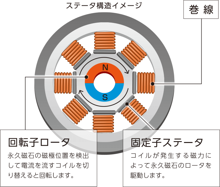
内部構造

[クリックで拡大]
永久磁石製のロータとステータ、ロータ位置検知用のホールICで構成されています。
ステータの構造:ブラシ付きモータとの違い
一般的なブラシ付モータは、モータ内部にブラシと呼ばれる部品があり、それが整流子と接触することで電流を切り替えてモーターを回転させる仕組みです。
機械的な接触を繰り返すため、ブラシの摩耗が発生し、定期的なメンテナンスが必要となります。
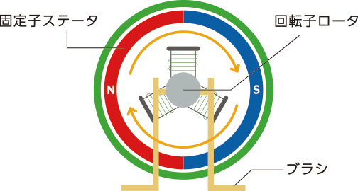
一方、DCブラシレスモータは、回転子が永久磁石・固定子がコイルとなっており、機械的な接点がありません。よって、ブラシ付モータのように部品の摩耗が発生せず、長寿命が期待できます。
ロータ位置検出機構の構造:サーボモータとの違い
DCブラシレスモータ・サーボモータともに、ロータの回転位置をドライバに常時フィードバックしているので、負荷変動時にも安定した速度制御を実現しています。
サーボモータは、ロータの位置検出に高精度なエンコーダを使用しているので、速度精度・トルク精度・停止精度に優れていますが、高コストです。
DCブラシレスモータは、高価なエンコーダの代わりにホールICを使用することで、サーボモータから速度制御の機能のみを取り出したものです。
低コストでサーボモータに近い高精度な速度制御を実現することができます。
