DCブラシレスドライバ

- つばき専用のDCブラシレスギヤモータ用ドライバです。
速度制御、位置決め運転、トルク制限運転や各種保護機能を搭載しています。 - ※必ず、モータ本体とドライバをセットで使用いただく必要があります。
- 専用ソフトウェアについてはこちらから

特長
-
・用途に合わせた運転パターンを選択可能
DCブラシレスハイポイドモートルとドライバを使用することで、様々な運転が簡単に実現できます。
【運転代表例】
・JOG運転
正転もしくは逆転信号をONにすると、モータが動き始める運転です。
ONのままであれば、設定した回転速度を維持して運転し続け、OFFにするとモータは減速しながら停止します。
【使用例】水平コンベヤ

運転動作例(正転時) 質量の異なる複数のワークを搬送した場合でも、速度が安定しており、
低速から高速まで幅広い可変速運転が可能です。・位置決め運転
位置決め運転モードでは、正転信号は運転開始信号として働きます。
JOG運転と異なり、位置決め運転は一度信号を入力すると設定した運転を一通り行った後に停止する運転です。
決められた動きを繰り返して運転したい場合に最適です。
【使用例】包装機

運転動作例(正転時) 包装機では、決められた位置にワークを停止させるために精度の高い間欠運転が必要となります。
送り量を一定となる包装機では、位置決め運転を使う事で正確な間欠送りが可能になります。・プログラム運転
事前にパラメータにて設定した順番通りに自動運転する機能です。
【使用例】ミキサー

プログラム運転によって自動で撹拌速度を切り替える事が可能となり、最適な運転を実現する事が可能です。
撹拌する材料に応じて複数の運転モードを設定する事で誰でも簡単にボタン1つで安定した品質を保ちます。・トルク制限運転
出力軸トルクを監視し、一定のトルクを超えないようにする運転です。
【使用例】フィルムの巻取り機

きれいに巻き取るためには一定のテンションを保ちながら巻き取る事が重要です。
しかし、引っ張りすぎると破断の原因となるため、トルク制限運転を活用する事で
一定以上のテンションにはならないように運転させる事が可能になります。 -
・過負荷保護機能を各種搭載
電流や電圧・温度等を検出しており、過負荷状態を検知して保護する事が可能です。
【使用例】チップコンベヤ

金属を加工した後の切粉を搬送するコンベヤです。
稼動状況を常時把握しているので、切粉を噛み込んだ際の過負荷を素早く検知して
停止やアラームを出すことが可能です。 -
・MODBUS-RTUのRS485の通信機能搭載
PLCと接続することで、通信機能による予知保全、遠隔監視を実現します。
・専用ソフトウェアを用いて各種設定値の変更が可能です。
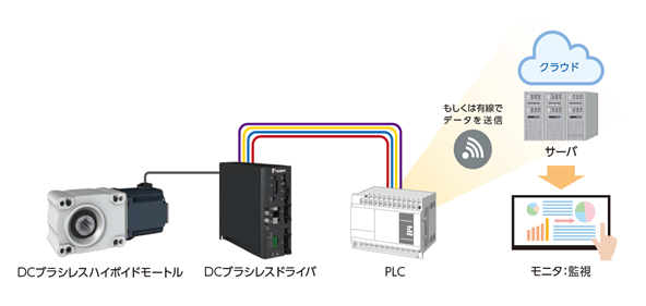
通信機能を搭載しており、モータの過熱、過負荷などを素早く検知し、モータを停止させることが可能です。
・PCとつなげることでパラメータの設定、専用ドライバのアップデートが可能です。

専用のPC用ソフトウェアを使用すれば、各パラメータの設定も簡単に変更できます。
今後、ドライバ用プログラムのアップデートにより新たな機能を追加していきます。専用ソフトウェアのダウンロード
インストール方法解説動画
■ソフトウェアバージョンアップのお知らせ
2024.03.01 誤記を修正しました。
(Ver2.0.1)2023.10.02 ・試運転機能追加※/メモリに書き込まない機能追加※しました。
・リアルタイムモニタ変更/IOモニタ追加※しました。
・エラーコード表示追加しました。
・パラメータ説明追加しました。
・動作の安定性向上を実施しました。
(Ver2.0.0)※2023年10月1日以降出荷のドライバから使用できます。
2023.04.26 動作の安定性向上を実施しました。
(Ver1.0.14.0)2023.03.27 プログラム運転ポイント数切替の変更、プログラム運転条件の追加、動作の安定性向上を実施しました。
(Ver1.0.13.0)アップデート版は、ソフトウェアの動作安定性が向上しておりますので、ご使用いただくことを推奨します。
※以前に出荷したドライバに関しても、アップデート版にて使用可能です。
対応ドライバは、2023年4月以降の出荷分になります。
但し、追加された一部機能は使用できません。詳細は取扱説明書を参照ください。 -
・簡易保持機能(電気的な保持ブレーキ)
モータ停止時にモータ軸が回転しないように位置保持制御を行う機能です。
電気的に軸を停止させるため、高頻度でモータを起動・停止させる運転でもブレーキの摩耗を心配する必要がありません。
簡易保持 電磁ブレーキ 保持の方法 電気式 機械式 電源OFF後の保持 不可 可能 音 電磁音あり 動作音あり 制御方法 特別な制御不要 制御必要
(インバータ駆動時)ブレーキ付をお使いの場合は、
この簡易保持機能により軸を停止させた後に、ブレーキを作動させる制御を行います。
これによりブレーキの長寿命化を実現しています。
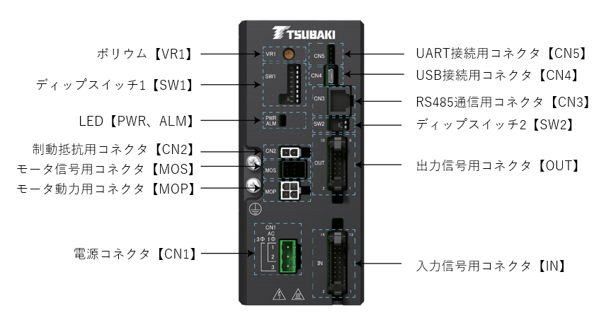
ドライバ詳細図
カタログ・取扱説明書
形番表示例
| DCRD | 020 | B | 10 | K |
| | | | | | |
| モータ容量 020:0.2kW 040:0.4kW 075:0.75kW |
| | | 電源電圧 |
| 電流使用 10:10A |
| 回生抵抗 K:回生抵抗対応仕様 |
| B:定格200~240V | ||||
| シリーズ名 DCブラシレスドライバ |
||||
商品一覧
※形番クリックで詳細情報を表示します。 全て開く 全て閉じる

| モータ容量 | 形番 |
|---|---|
| 0.2kW | DCRD020B10K |
| 0.4kW | DCRD040B10K |
| 0.75kW | DCRD075B10K |
制御部オプション
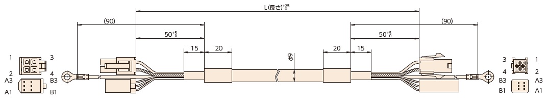
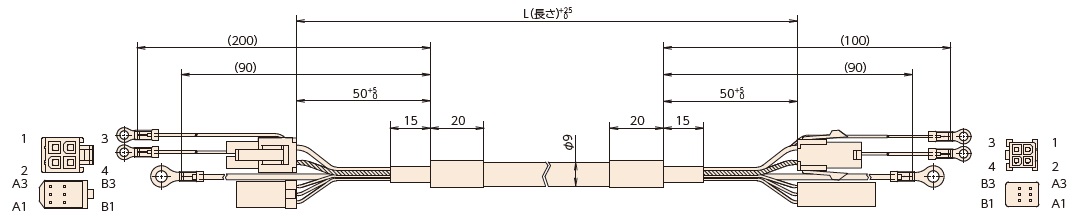
DCブラシレスハイポイドモートル延長ケーブル
・モータは専用ケーブルとなっております。延長する際は本ケーブルを使用しコネクタ同士を接続下さい。
・アース線は、丸形圧着端子同士をネジ止めにて延長下さい。
・延長ケーブルを継ぎ足して延長するときは、ケーブルの全長を10m以下にしてください。
・ブレーキ無
| 形番 | L m | PDF図面 | 希望価格(税別) | 納期 |
|---|---|---|---|---|
| DCCM0005 | 0.5 | ¥5,250 | 1週間 | |
| DCCM0010 | 1.0 | ¥6,300 | 1週間 | |
| DCCM0020 | 2.0 | ¥8,750 | 1週間 | |
| DCCM0050 | 5.0 | ¥16,800 | 1週間 | |
| DCCM0100 | 10.0 | ¥28,000 | 1週間 |
・ブレーキ付
| 形番 | L m | PDF図面 | 希望価格(税別) | 納期 |
|---|---|---|---|---|
| DCCM0005B | 0.5 | ¥5,600 | 1週間 | |
| DCCM0010B | 1.0 | ¥6,650 | 1週間 | |
| DCCM0020B | 2.0 | ¥8,920 | 1週間 | |
| DCCM0050B | 5.0 | ¥17,200 | 1週間 | |
| DCCM0100B | 10.0 | ¥28,900 | 1週間 |
DCブラシレスドライバ延長ケーブル
・延長ケーブルを継ぎ足して延長するときは、ケーブルの全長を10m以下にしてください。
・入力信号用
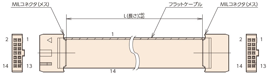
| 形番 | L m | PDF図面 | 希望価格(税別) | 納期 |
|---|---|---|---|---|
| DCCN0005 | 0.5 | ¥2,800 | 1週間 | |
| DCCN0010 | 1.0 | ¥3,320 | 1週間 | |
| DCCN0020 | 2.0 | ¥4,200 | 1週間 |
・出力信号用
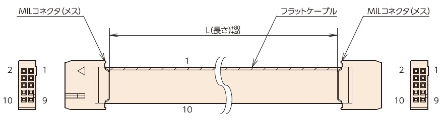
| 形番 | L m | PDF図面 | 希望価格(税別) | 納期 |
|---|---|---|---|---|
| DCCT0005 | 0.5 | ¥2,620 | 1週間 | |
| DCCT0010 | 1.0 | ¥2,800 | 1週間 | |
| DCCT0020 | 2.0 | ¥3,320 | 1週間 |
・通信用
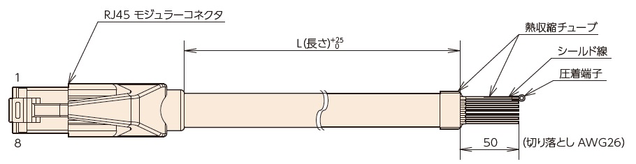
| 形番 | L m | PDF図面 | 希望価格(税別) | 納期 |
|---|---|---|---|---|
| DCCS0005 | 0.5 | ¥5,070 | 1週間 | |
| DCCS0010 | 1.0 | ¥6,650 | 1週間 | |
| DCCS0020 | 2.0 | ¥9,800 | 1週間 |
注)本ケーブルはB結線を使用しています。A結線で接続すると通信不良、部品破損のおそれがありますので、使用しないで下さい。
DINレール取付金具
・DINレール(35mm)に、DCBLドライバを取付けるための金具となります。
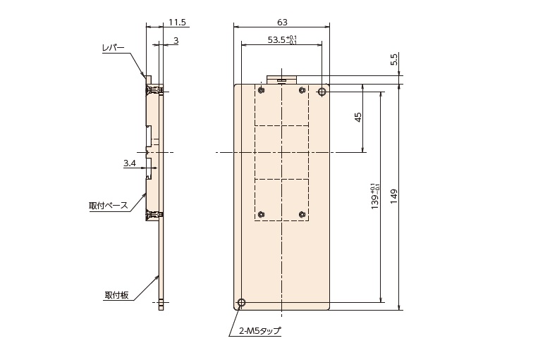
| 形番 | PDF図面 | 希望価格(税別) | 納期 |
|---|---|---|---|
| DCDN075 | ¥9,100 | 1週間 |
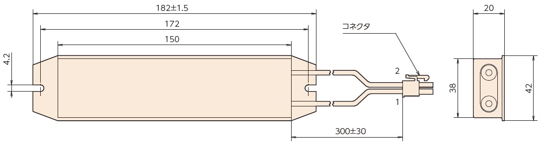
回生抵抗器
・DCBLドライバに、コネクタを接続してご使用下さい。
| 形番 | 容量 W | 抵抗値 Ω | PDF図面 | 希望価格(税別) | 納期 |
|---|---|---|---|---|---|
| DCKR075 | 120 | 200 | ¥14,900 | 1週間 |
