大形コンベヤスプロケット フィットボア®

- 大形コンベヤチェーン専用のスプロケットです。
- フィットボアは軸穴仕上げの完成品です。
- お届け後すぐに使用いただけます。
- 加工内容を記号化していますので、形番だけで簡単に手配できます。

特長
- ・軸穴加工やキー溝加工内容が商品名でコード化されているため、お客様手配内容が正確に伝達できます。
- ・軸穴、キー溝、タップ穴等が加工済みですので、お客様に到着後そのままご使用いただけます。
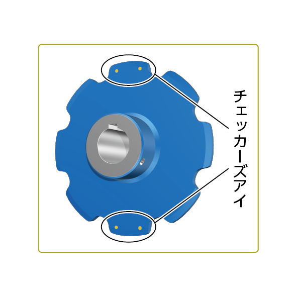
- ・歯の使用限界が一目でわかるチェッカーズアイをオプションで選んでいただけます。
カタログ・取扱説明書
形番表示例
| RF17200S12T-BW1 | Q | - | H | 090 | N | - | J | 25 | D3 | M16 | - | H1 | - | L2 | -E | |
| | 本体形番 |
| | | | |
| 軸穴公差 H:H8 |
| | | | | | | |
| 軸穴部面取 N:つばき標準 A:C1 B:C2 C:C3 |
| | | | |
| キー溝幅 |
| | | | |
| タップサイズ |
| 並列記号 (2) |
| 塗装記号 (3) |
| | | | |
|||||
| 歯先硬化 N:歯先硬化なし Q:歯先硬化仕様 |
キー溝公差 W:キー溝なし J:新JIS Js9 P:新JIS P9 E:旧JIS E9 |
タップ穴加工仕様 (1) |
チェッカーズアイ 無記:なし E:チェッカーズアイ |
|||||||||||||
| 軸穴径 mm |
||||||||||||||||
| (1) タップ穴加工仕様 | (2) 並列記号 *2個一組 | |||||
|---|---|---|---|---|---|---|

※並列使用でH1とH3の場合のタップ配置は |
ハブ取付方向イメージ図 
※H1、H3の場合、タップ配置は半数勝手違いとします。 半数勝手違い 並列で使用する一般のスプロケットはタップ配置を対称に加工します。 例:□□□D2M16-H1-L0の場合 
|
|||||
| (3) 塗装記号 | ||||||

|
商品一覧
メートル系ピッチ
| 形番 | Rローラ | Fローラ | Sローラ | |||||||||
|---|---|---|---|---|---|---|---|---|---|---|---|---|
| 歯数 | 歯数 | 歯数 | ||||||||||
| 6 | 8 | 10 | 12 | 6 | 8 | 10 | 12 | 6 | 8 | 10 | 12 | |
| RF03075 | ● | ● | ● | ● | ● | ● | ● | ● | ● | ● | ● | ● |
| RF03100 | ● | ● | ● | ● | ● | ● | ● | ● | ● | ● | ● | ● |
| RF05075 | - | - | - | - | - | - | - | - | - | ● | ● | ● |
| RF05100 | ● | ● | ● | ● | ● | ● | ● | ● | ● | ● | ● | ● |
| RF05125 | ● | ● | ● | ● | ● | ● | ● | ● | ● | ● | ● | ● |
| RF05150 | ● | ● | ● | ● | ● | ● | ● | ● | ● | ● | ● | ● |
| RF08125 | ● | ● | ● | ● | ● | ● | ● | ● | ● | ● | ● | ● |
| RF08150 | ● | ● | ● | ● | ● | ● | ● | ● | ● | ● | ● | ● |
| RF10100 | ● | ● | ● | ● | - | - | - | - | ● | ● | ● | ● |
| RF10125 | ● | ● | ● | ● | ● | ● | ● | ● | ● | ● | ● | ● |
| RF10150 | ● | ● | ● | ● | ● | ● | ● | ● | ● | ● | ● | ● |
| RF12200 | ● | ● | ● | ● | ● | ● | ● | ● | ● | ● | ● | ● |
| RF12250 | ● | ● | ● | ● | ● | ● | ● | ● | ● | ● | ● | ● |
| RF17200 | ● | ● | ● | ● | ● | ● | ● | ● | ● | ● | ● | ● |
| RF17250 | ● | ● | ● | ● | ● | ● | ● | ● | ● | ● | ● | ● |
| RF17300 | ● | ● | ● | ● | ● | ● | ● | ● | ● | ● | ● | ● |
インチ系ピッチ
| 形番 | Rローラ | Fローラ | Sローラ | |||||||||
|---|---|---|---|---|---|---|---|---|---|---|---|---|
| 歯数 | 歯数 | 歯数 | ||||||||||
| 6 | 8 | 10 | 12 | 6 | 8 | 10 | 12 | 6 | 8 | 10 | 12 | |
| RF430 | ● | ● | ● | ● | - | - | - | - | ● | ● | ● | ● |
| RF204 | - | - | - | - | - | - | - | - | - | ● | ● | ● |
| RF450 | ● | ● | ● | ● | ● | ● | ● | ● | ● | ● | ● | ● |
| RF650 | ● | ● | ● | ● | ● | ● | ● | ● | ● | ● | ● | ● |
| RF214 | ● | ● | ● | ● | - | - | - | - | ● | ● | ● | ● |
| RF205 | - | - | - | - | - | - | - | - | - | ● | ● | ● |
| RF6205 | ● | ● | ● | ● | ● | ● | ● | ● | ● | ● | ● | ● |
| RF212 | ● | ● | ● | ● | - | - | - | - | ● | ● | ● | ● |
加工内容
※クリックで詳細情報を表示します。

| 軸穴加工(L) | キー溝加工(K) | タップ穴加工(D) |
|---|---|---|
 |
 |
 |
|
・加工寸法は整数のみ1mm単位 ・加工公差・・・H8のみ |
・平行キー溝のみ
・加工公差・・・選択可 |
・加工サイズ選択可 ・加工箇所(2ヵ所まで)選択可 ・六角穴付き止めねじ付属(くぼみ先) |
JS9・P9の場合(新JIS)
| 適用軸穴径 (mm) |
キー溝幅 (mm) |
タップサイズ (つばき標準) |
選択サイズ |
|---|---|---|---|
| 19~22 | 6 | M6 | M5 |
| 22~30 | 8 | M6 | M5, M8 |
| 30~38 | 10 | M8 | M6, M10 |
| 38~44 | 12 | M8 | M6, M10 |
| 44~50 | 14 | M8 | M6, M10 |
| 50~58 | 16 | M10 | M8, M12 |
| 58~65 | 18 | M10 | M8, M12 |
| 65~75 | 20 | M12 | M10, M16 |
| 75~85 | 22 | M12 | M10, M16 |
| 85~95 | 25 | M16 | M12, M20 |
| 95~110 | 28 | M16 | M12, M20 |
| 110~130 | 32 | M20 | M16 |
| 130~150 | 36 | M20 | M16 |
| 150~170 | 40 | M20 | M16 |
| 170~175 | 45 | M24 | M20 |
E9の場合(旧JIS)
| 適用軸穴径 (mm) |
キー溝幅 (mm) |
タップサイズ つばき標準 |
選択サイズ |
|---|---|---|---|
| 19~20 | 5 | M5 | M4 |
| 21~30 | 7 | M6 | M5 |
| 31~40 | 10 | M8 | M6, M10 |
| 41~50 | 12 | M8 | M6, M10 |
| 51~60 | 15 | M8 | M6, M10 |
| 61~70 | 18 | M10 | M8, M12 |
| 71~80 | 20 | M12 | M10, M16 |
| 81~95 | 24 | M12 | M10, M16 |
| 96~110 | 28 | M16 | M12, M20 |
| 111~125 | 32 | M20 | M16 |
| 126~140 | 35 | M20 | M16 |
| 141~160 | 38 | M20 | M16 |
| 161~175 | 42 | M20 | M16 |
| 適用軸穴径(mm) | 面取り |
|---|---|
| ~50 | C0.6 |
| 51~80 | C1 |
| 81~120 | C1.6 |
| 121~175 | C2 |
| 軸穴径 | 選択できる面取量 | |||
|---|---|---|---|---|
| ~44 | N | A | B | - |
| 45~ | N | A | B | C |
| H0 | なし |
| H1 | ハブ取付方向:内-内 |
| H2 | ハブ取付方向:同方向 |
| H3 | ハブ取付方向:外-外 |
- ・並列使用はスプロケット2個を同軸上でご使用の場合、指定された取付方向でキー溝位置を合わせて加工します。
- ・ハブ取付方向は下図3パターンより選択ください。
ハブ取付方向イメージ図
| L0 | 塗装なし(防錆油塗布) |
| L1 | ラッカー塗装(標準品塗装色) |
| L2 | ラッカー塗装(チェッカーズアイ用塗装色) |
・チェッカーズアイ仕様で塗装ありの場合、L2:ブルー色となります。
| E | チェッカーズアイ |
| 無記 | なし |
- ・黄銅製ピン埋込み仕様。
- ・スプロケットの歯部両側面に各2ヵ所/0度と180度を目安として2歯に埋込み。
キー溝加工ありの場合、1ヵ所はキー溝上部の歯に埋込み