ショックガード® TGHシリーズ
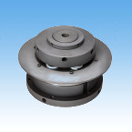
- モータ直結などの高速回転軸に取付可能で、高トルクにも対応可能なタイプ
- ・繰返し作動トルク精度は±5%以内です。
- ・ベーシックタイプ以外にも、カップリングタイプやプーリタイプも取り揃えています。
- ・自動復帰をしないため、過負荷によるトリップ後、駆動側の回転が被動側に伝わらない機能です。
- ・復帰方法は、ワンポジション復帰(1か所のみで復帰)かランダム復帰から選択可能です。
・ワンポジション復帰:1カ所だけで復帰します。位相合わせに適しています。
・ランダム復帰:複数個所で復帰できます。
構造
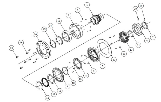
| (1) | ハブ | (2) | ドライブプレート | (3) | スライドプレート | (4) | 中間プレート | (5) | バックアップリング |
| (6) | トルク調節ナット | (7) | ロックカラー | (8) | ドライブボール(鋼球A) | (9) | 鋼球B | (10) | ボールベアリング |
| (11) | スラストベアリング | (12) | スラストワッシャ | (13) | サポートリング A | (14) | スナップリング A | (15a,b) | スプリングピン A |
| (16a,b) | スプリングピン C | (17) | コイルバネ | (18) | コイルバネ(インナ) | (19) | - | (20) | 六角穴付止ネジ |
| (21) | 六角穴付止ネジ | (22) | トルク調節スペーサ | (23) | アダプタ | (24) | スプリングピン B | (25) | 六角穴付ボルト |
| (26) | スプリングワッシャ | (27a,b) | シムリング | (28) | 検知板 | (29) | 六角穴付ボルト | (30a,b) | テーパローラベアリング |
| (31) | 加圧プレート | (32) | 六角穴付きボルト | (33) | スプリングワッシャ | (34) | ベアリングカバー | (35) | 六角穴付皿ボルト |
| (36) | スプリングホルダ | (37) | 六角ボルト | (38) | 平ワッシャ | (39) | キープレート | (40) | 六角穴付ボルト |
| (41) | 六角穴付止ネジ | (42a,b) | グリスニップル |
作動原理
通常時(噛合い時)
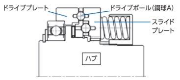
TGHシリーズは、数個のドライブボール(鋼球A)をドライブプレートとスライドプレートで挟み込み、バネで加圧された状態で動力伝達されます。
動力は、ハブから入り、インボリュートスプラインで噛合ったスライドプレートに伝えられ、ドライブボール(鋼球A)を介してドライブプレートに伝達されます。
被駆動側にあたるプーリやカップリングは、ドライブプレートに取り付けられたアダプタにスプリングピンとボルトで固定します。
過負荷時(トリップ時)
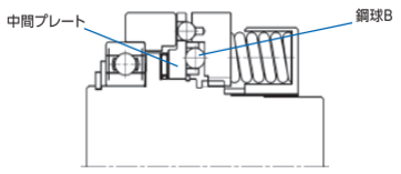
過負荷が発生するとドライブボール(鋼球A)は、スライドプレートをばね側に押し上げ、回転しながらドライブプレートの各ポケットから飛び出し動力を遮断します。
この後、空転を続けるとドライブボール(鋼球A)は、スライドプレートの深いポケットに入りますが、中間プレート上の鋼球Bがスライドプレートに加わるバネ荷重を支える状態となります。
そのため、ドライブボール(鋼球A)はスライドプレートの深いポケットに入り込んだままとなり、空転を続けてもドライブプレートに動力を伝達せず、空転状態を続けます。
仕様(標準機種)
| シリーズ | 設定トルク範囲 N・m | 繰返し作動トルク精度 | 復帰方法 |
|---|---|---|---|
| ベーシックタイプ | 32~5050 | ±5% | 手動 |
| カップリング(NER)タイプ | 32~5050 | ||
| カップリング(AFT)タイプ | 32~5050 | ||
| プーリタイプ | 32~2460 |
■ベーシックタイプ:お客様でギヤやスプロケットを直接取付可能です。
■カップリング(NER)タイプ:NERカップリングを組合せたタイプです。高剛性で、ノンバックラッシが特長です。
■カップリング(AFT)タイプ:ATRAFLEXカップリングを組合せたタイプです。特長は振動減衰性と衝撃吸収に優れ、取り付けが容易、コンパクトにできます。
■プーリタイプ:プーリを組合わせたタイプです。
カタログ・取扱説明書
形番表示
※ベーシックタイプ
| TGH | 75 | - | M | B | S | - | T | H | 70 | P | D2 | - | N1000 |
| | シリーズ |
| サイズ 28 40 50 75 100 |
| バネ種類 L:弱バネ M:中バネ H:強バネ U:超強バネ |
| | | | | | | | |
| | | | |
| ショックガード側 T |
| 軸穴径公差 F:F7 G:G7 H:H7 J:JS7 P:P7 |
| 軸穴径 (mm) |
| | | | |
| 止ネジ位置 D2 |
| トルク設定値 (N・m) |
|||
| 復帰方法 記号なし:ランダム復帰 S:ワンポジション復帰 |
キー溝公差 J:新JIS Js9 P:新JIS P9 F:旧JIS F7 E:旧JIS E9 |
||||||||||||
| タイプ B:ベーシックタイプ |
|||||||||||||
※カップリングタイプ
| TGH | 50 | - | L | CN | S | - | T | H | 30 | J | D2 | X | C | H | 60 | J | D3 | - | N200 |
| | シリーズ |
| サイズ 28 40 50 75 100 |
| バネ種類 L:弱バネ M:中バネ H:強バネ U:超強バネ |
| | | | | | | | |
| | | | | | | | | | |
| | | | | | | | |
| 軸穴径公差 F:F7 G:G7 H:H7 J:JS7 P:P7 |
| 軸穴径 (mm) |
| | | | |
| 止ネジ位置 D2 |
| | | | | | | | |
| 軸穴径公差 F:F7 G:G7 H:H7 J:JS7 P:P7 |
| 軸穴径 (mm) |
| | | | |
| 止ネジ位置 D0~D8 |
| トルク設定値 (N・m) |
||||
| キー溝公差 J:新JIS Js9 P:新JIS P9 F:旧JIS F7 E:旧JIS E9 |
キー溝公差 J:新JIS Js9 P:新JIS P9 F:旧JIS F7 E:旧JIS E9 |
||||||||||||||||||
| タイプ CN:カップリング(NER)タイプ CA:カップリング(AFT)タイプ |
ショックガード側 T |
カップリング側 C |
|||||||||||||||||
| | 復帰方法 記号なし:ランダム復帰 S:ワンポジション復帰 |
|||||||||||||||||||
※プーリタイプ
| TGH | 50 | - | H | P | S | - | T | H | 100 | J | D0 | - | N1500 | -TK |
| | シリーズ |
| サイズ 28 40 50 75 |
| バネ種類 L:弱バネ M:中バネ H:強バネ U:超強バネ |
| | | | | | | | |
| | | | |
| ショックガード側 T |
| 軸穴径公差 F:F7 G:G7 H:H7 J:JS7 P:P7 |
| 軸穴径 (mm) |
| | | | |
| 止ネジ位置 D0 |
| トルク設定値 (N・m) |
| 特形 |
|||
| 復帰方法 記号なし:ランダム復帰 S:ワンポジション復帰 |
キー溝公差 J:新JIS Js9 P:新JIS P9 F:旧JIS F7 E:旧JIS E9 |
|||||||||||||
| タイプ P:プーリタイプ |
||||||||||||||
製品形番一覧
※形番クリックで詳細情報を表示します。
| サイズ | バネ種類 | トルク N・m |
ベーシックタイプ | プーリタイプ | |||||
|---|---|---|---|---|---|---|---|---|---|
| 軸穴径範囲 mm |
形式 | 軸穴径範囲 mm |
形式 | ||||||
| 最小 | 最大 | 最小 | 最大 | 最小 | 最大 | ||||
| 28 | L | 32 | 80 | 12 | 28 | TGH28-LB | 12 | 36 (35) |
TGH28-LP |
| M | 64 | 160 | TGH28-MB | TGH28-MP | |||||
| H | 96 | 240 | TGH28-HB | TGH28-HP | |||||
| U | 128 | 320 | TGH28-UB | TGH28-UP | |||||
| 40 | L | 60 | 150 | 17 | 40 | TGH40-LB | 17 | 50 | TGH40-LP |
| M | 120 | 300 | TGH40-MB | TGH40-MP | |||||
| H | 180 | 450 | TGH40-HB | TGH40-HP | |||||
| U | 280 | 700 | TGH40-UB | TGH40-UP | |||||
| 50 | L | 80 | 200 | 20 | 50 | TGH50-LB | 20 | 58 (56) |
TGH50-LP |
| M | 160 | 400 | TGH50-MB | TGH50-MP | |||||
| H | 320 | 800 | TGH50-HB | TGH50-HP | |||||
| U | 480 | 1200 | TGH50-UB | TGH50-UP | |||||
| 75 | L | 246 | 615 | 50 | 75 (72) |
TGH75-LB | 50 | 80 (79) |
TGH75-LP |
| M | 492 | 1230 | TGH75-MB | TGH75-MP | |||||
| H | 738 | 1845 | TGH75-HB | TGH75-HP | |||||
| U | 984 | 2460 | TGH75-UB | TGH75-UP | |||||
| 100 | L | 400 | 1000 | 60 | 100 (95) |
TGH100-LB | - | ||
| M | 800 | 2000 | TGH100-MB | ||||||
| H | 1600 | 4000 | TGH100-HB | ||||||
| U | 2020 | 5050 | TGH100-UB | ||||||
| サイズ | バネ種類 | トルク N・m |
カップリング(NER)タイプ | カップリング(AFT)タイプ | |||||||||
|---|---|---|---|---|---|---|---|---|---|---|---|---|---|
| ショックガード側 軸穴径範囲 mm |
カップリング側 軸穴径範囲 mm |
形式 | ショックガード側 軸穴径範囲 mm |
カップリング側 軸穴径範囲 mm |
形式 | ||||||||
| 最小 | 最大 | 最小 | 最大 | 最小 | 最大 | 最小 | 最大 | 最小 | 最大 | ||||
| 28 | L | 32 | 80 | 12 | 28 | 25 | 65 (61) |
TGH28-LCN | 12 | 28 | 17 | 55 | TGH28-LCA |
| M | 64 | 160 | TGH28-MCN | TGH28-MCA | |||||||||
| H | 96 | 240 | TGH28-HCN | TGH28-HCA | |||||||||
| U | 128 | 320 | TGH28-UCN | TGH28-UCA | |||||||||
| 40 | L | 60 | 150 | 17 | 40 | 25 | 85 (80) |
TGH40-LCN | 17 | 40 | 22 | 60 | TGH40-LCA |
| M | 120 | 300 | TGH40-MCN | TGH40-MCA | |||||||||
| H | 180 | 450 | TGH40-HCN | TGH40-HCA | |||||||||
| U | 280 | 700 | TGH40-UCN | TGH40-UCA | |||||||||
| 50 | L | 80 | 200 | 20 | 50 | 50 | 90 (84) |
TGH50-LCN | 20 | 50 | 22 | 80 | TGH50-LCA |
| M | 160 | 400 | TGH50-MCN | TGH50-MCA | |||||||||
| H | 320 | 800 | TGH50-HCN | TGH50-HCA | |||||||||
| U | 480 | 1200 | TGH50-UCN | TGH50-UCA | |||||||||
| 75 | L | 246 | 615 | 50 | 75 (72) |
60 | 105 (99) |
TGH75-LCN | 50 | 75 (72) |
42 | 110 | TGH75-LCA |
| M | 492 | 1230 | TGH75-MCN | TGH75-MCA | |||||||||
| H | 738 | 1845 | TGH75-HCN | TGH75-HCA | |||||||||
| U | 984 | 2460 | TGH75-UCN | TGH75-UCA | |||||||||
| 100 | L | 400 | 1000 | 60 | 100 (95) |
80 | 125 (119) |
TGH100-LCN | 60 | 100 (95) |
42 | 140 | TGH100-LCA |
| M | 800 | 2000 | TGH100-MCN | TGH100-MCA | |||||||||
| H | 1600 | 4000 | TGH100-HCN | TGH100-HCA | |||||||||
| U | 2020 | 5050 | TGH100-UCN | TGH100-UCA | |||||||||
※( )部は旧JIS加工時の最大軸穴径です。新JISは「JIS B 1301-1996]、旧JISは「JIS B 1301-1959」に準拠します。
オプション
TGセンサ
ショックガード専用の近接スイッチ方式の過負荷検出センサです。ショックガードの過負荷(プレートの軸方向の移動)を検出して、モータの停止や警報を出すことができます。

| 交流タイプ | 直流タイプ | ||
|---|---|---|---|
| 形番 | TGS8 | TGS8DN | |
| 電源 電圧 |
定格 | AC24~240V | - |
| 使用可能範囲 | AC20~264V(50/60Hz) | DC10~30V | |
| 消費電流 | 1.7mA以下(at AC200V) | 16mA以下 | |
| 制御出力(開閉容量) | 5~100mA | 最大200mA | |
| 表示灯 | 動作表示 | ||
| 使用周囲温度 | -25~+70℃(ただし氷結しないこと) | ||
| 使用周囲湿度 | 35~95% RH | ||
| 出力形態 | - | NPN | |
| 動作形態 | NC(センサプレートを検知していない時の出力開閉状態を表します) | ||
| 絶縁抵抗 | 50MΩ以上(DC500Vメガにて)充電部一括とケース間 | ||
| 質量 | 約45g(コード長2m) | 約56g(コード長2m) | |
| 残留電圧 | >> 特性データ参照 | 2.0V以下(負荷電流200mA・コード長2m) | |
| 取扱説明書 | TGセンサ TGS8 | TGセンサ TGS8DN | |
負荷残留電圧特性

寸法図
交流タイプ TGS8

直流タイプ TGS8DN

選定計算
つばきショックガード全シリーズを対象に、使用条件に合うショックガードを選定いたします。
本ページ上部の「選定計算」のタブをクリックしてください。
このページの上へ戻る