ショックガード® TGFシリーズ

- 復帰位置精度に優れたタイプ
- ・ドライブプレートの支持ベアリングには予圧をかけることで隙間を無くし、取付面を研磨することによって出力の取付面精度が良くなっています。
さらに振れ精度が必要な場合は、組立後に穴基準で取付面を研磨し組み立てによる僅かな振れの誤差を無くすことも可能です。 - ・バックラッシが極小で復帰位置精度が良く、インデクサに最適です。
- ・過負荷の原因を取除いた後、駆動側を回転するだけで自動的に再度噛合いします。
- ・トルクの伝達素子になっているボール&ポケットの配列は、1カ所でしか噛合わない独特の組合せになっています。
構造
TGF20~45
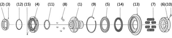
(1) ハブ (2) エンドナット (3) 六角穴付止ネジ (4) ドライブプレート (5) スライドプレート (6) 調節ナット
(7) コイルバネ (8) ドライブボール(鋼球A) (9) スナップリング (10) 六角穴付止ネジ (11) 鋼球B (12) 鋼球C
(13) ハウジング (14) スラストベアリング (15) 六角穴付止ネジ
TGF65~90
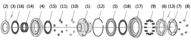
(1) ハブ (2) エンドナット (3) 六角穴付止ネジ (4) ドライブプレート (5) スライドプレート (6) 調節ナット
(7) スプリングホルダ (8) 六角穴付皿ネジ (9) コイルバネ (10) ドライブボール(鋼球A) (11) ブッシュ
(12) スナップリング (13) 六角穴付止ネジ (14) ラジアルベアリング (15) スラストベアリングA
(16) スラストベアリングA (17) ハウジング (18) スラストベアリングB
作動原理
TGFシリーズの作動原理をアニメーションでご覧ください。
通常時(噛合い時)
TGFシリーズの動力は、ハブから入り、ドライブボールを介して出力側のドライブプレートに伝達されます。(またはその逆)
このドライブプレートにスプロケットやタイミングプーリをボルトで直接取付け使用します。
ハブのフランジ部に数個のドライブボールが入る穴が設けられ、そこにドライブボールが配置されています。出力側となるドライブプレートには、ドライブボールが入るポケットが有り、
ドライブボールをコイルバネでスラストレースを介して加圧された状態で動力伝達されます。
過負荷時(トリップ時)
過負荷が発生するとドライブボールは、スラストレースをコイルバネ側に押上げ、回転しながらドライブ
プレートのポケットから飛出し動力を遮断します。
この時、カバーがコイルバネ側に移動するため、この移動量をTGセンサなどで検知することにより、過負荷発生後、駆動源を自動的に停止させることが簡単にできます。
復帰方法
過負荷後、再起動すれば自動的に一回転以内で定位置復帰します。
TGFシリーズは作動後回転を続けると連続復帰しますので過負荷発生後、TGセンサなどで過負荷を検出し、即時駆動源を停止させてください。
仕様(標準機種)
| 設定トルク範囲 N・m | 繰返し作動トルク精度 | バックラッシ | 復帰方法 |
|---|---|---|---|
| 6.0~4900 | ±5% | 極小 | 自動 |
■タイプ2:タイミングプーリなどを直接取付可能。軸用止めネジを外部から締付可能。
■タイプ3:タイプ2より薄型でパワーロック取付に最適。(詳細はリンク先を参照ください)
■タイプ5:エクトフレックスを組合せたカップリングタイプで角度の誤差を許容。
■タイプ7:エクトフレックスを組合せたカップリングタイプで角度と平行度の誤差を許容。
カタログ・取扱説明書
形番表示
※単体タイプ
| TGF | 20 | - | L | 2 | - | TH20JD2 | - | N19 |
| | シリーズ |
| サイズ |
| | | | |
| タイプ 2:タイプ 2 3:タイプ 3 |
| 軸穴記号 |
| トルク設定値 N・m |
|||
| バネ強さ L:弱バネ M:中バネ H:強バネ |
||||||||
※カップリングタイプ
| TGF | 20 | - | L | 5 | - | TH20PD2 | X | CH30PD2 | - | N18 |
| | シリーズ |
| サイズ |
| | | | |
| タイプ 5:タイプ 5 7:タイプ 7 |
| ショックガード側 軸穴記号 |
| カップリング側 軸穴記号 |
| トルク設定値 N・m |
||||
| バネ強さ | ||||||||||
| 軸穴径公差 | 軸穴径 | キー溝公差 | 止ネジ位置 | |
|---|---|---|---|---|
| T | H | 20 | P | D2 |
| C | H | 30 | P | D2 |
| T:ショックガード側 C:カップリング側 | F:F7 G:G7 H:H7 |
軸穴径は 1mm単位です |
J:新JIS Js9(標準) P:新JIS P9 F:旧JIS F7 |
 [クリックで拡大] |
注)ショックガード側の止めねじ位置は調節ナット側から見た位置、カップリング側の止めねじ位置はハブ端面から見た位置です。
■つばき形番ナビ
製品形番一覧
※形番クリックで詳細情報を表示します。
| 設定トルク範囲 N・m |
単体 | カップリングタイプ | ||||
|---|---|---|---|---|---|---|
| 軸穴径範囲 mm |
形番 | カップリング側 軸穴径範囲 mm |
形番 | |||
| タイプ2 | タイプ3 | タイプ5 | タイプ7 | |||
| 6.0~20 | 10~20 | TGF20-L2 | TGF20-L3 | 17~42 | TGF20-L5 | TGF20-L7 |
| 12~40 | TGF20-M2 | TGF20-M3 | TGF20-M5 | TGF20-M7 | ||
| 24~80 | TGF20-H2 | TGF20-H3 | TGF20-H5 | TGF20-H7 | ||
| 10~74 | 12~30 | TGF30-L2 | TGF30-L3 | 17~60 | TGF30-L5 | TGF30-L7 |
| 20~147 | TGF30-M2 | TGF30-M3 | TGF30-M5 | TGF30-M7 | ||
| 40~294 | TGF30-H2 | TGF30-H3 | TGF30-H5 | TGF30-H7 | ||
| 30~156 | 22~45 | TGF45-L2 | TGF45-L3 | 27~74 | TGF45-L5 | TGF45-L7 |
| 60~313 | TGF45-M2 | TGF45-M3 | TGF45-M5 | TGF45-M7 | ||
| 120~568 | TGF45-H2 | TGF45-H3 | TGF45-H5 | TGF45-H7 | ||
| 50~269 | 32~65 | TGF65-L2 | TGF65-L3 | 47~95 | TGF65-L5 | TGF65-L7 |
| 100~539 | TGF65-M2 | TGF65-M3 | TGF65-M5 | TGF65-M7 | ||
| 200~1078 | TGF65-H2 | TGF65-H3 | TGF65-H5 | TGF65-H7 | ||
| 300~1225 | 47~90 | TGF90-L2 | TGF90-L3 | 52~118 | TGF90-L5 | TGF90-L7 |
| 600~2450 | TGF90-M2 | TGF90-M3 | TGF90-M5 | TGF90-M7 | ||
| 1200~4900 | TGF90-H2 | TGF90-H3 | TGF90-H5 | TGF90-H7 | ||
オプション
TGセンサ
ショックガード専用の近接スイッチ方式の過負荷検出センサです。ショックガードの過負荷(プレートの軸方向の移動)を検出して、モータの停止や警報を出すことができます。

| 交流タイプ | 直流タイプ | ||
|---|---|---|---|
| 形番 | TGS8 | TGS8DN | |
| 電源 電圧 |
定格 | AC24~240V | - |
| 使用可能範囲 | AC20~264V(50/60Hz) | DC10~30V | |
| 消費電流 | 1.7mA以下(at AC200V) | 16mA以下 | |
| 制御出力(開閉容量) | 5~100mA | 最大200mA | |
| 表示灯 | 動作表示 | ||
| 使用周囲温度 | -25~+70℃(ただし氷結しないこと) | ||
| 使用周囲湿度 | 35~95% RH | ||
| 出力形態 | - | NPN | |
| 動作形態 | NC(センサプレートを検知していない時の出力開閉状態を表します) | ||
| 絶縁抵抗 | 50MΩ以上(DC500Vメガにて)充電部一括とケース間 | ||
| 質量 | 約45g(コード長2m) | 約56g(コード長2m) | |
| 残留電圧 | >> 特性データ参照 | 2.0V以下(負荷電流200mA・コード長2m) | |
| 取扱説明書 | TGセンサ TGS8 | TGセンサ TGS8DN | |
負荷残留電圧特性

寸法図
交流タイプ TGS8

直流タイプ TGS8DN

選定計算
つばきショックガード全シリーズを対象に、使用条件に合うショックガードを選定いたします。
本ページ上部の「選定計算」のタブをクリックしてください。
このページの上へ戻るトルク調整
1.トルク相関図から必要トルクに対応するトルクスケールの値を読取り、調節ナットをこの値まで締込んでください。
調節ナットを締込むには、ナットの外周の穴に引掛スパナか丸棒を差込んで回してください。
(注)TGF30、45 サイズで必要トルクが高い場合(200N・m 以上)は、専用の引掛スパナ(別売品) を使用してください。
なお、TGF65、90 サイズで必要トルクが高い場合は、ボルトを一旦緩めて調節ナットを必要とするトルクスケールまで六角穴付止ネジで調節ナットを固定し、最後にボルトを完全に
締込む事により容易にトルク調整ができます。
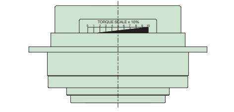
⇐ トルクスケール
製品のトルクは下の相関図と必ずしも一致しませんので目安として使用してください。
2.トルクが決定しましたらその値を銘板に追記しておくことにより、メンテナンスの時、分解しても容易に前の設定トルクに戻す事ができます。
なお、ナットにハブの端面に合マークを刻印しておけばより正確に再現できます。
トルク相関図

