| Q1 |
タイミングプーリのアライメント調整の必要性は? |
| A1 |
タイミングベルトは、タイミングプーリのアライメントが正しい場合でもタイミングプーリの中央で走行せず、どちらかに片寄る性質があります。
その力は非常に弱いものですが、タイミングプーリのアライメントが悪いと、タイミングプーリの端に寄って走行し、ガイドフランジに強く押し付けられて損傷、切断する可能性があります。
また、ガイドフランジが脱落する可能性があります。
タイミングプーリのアライメントは下表の許容差内に調整してください。
| ベルトサイズ |
全品種 |
| ベルト幅 mm |
30以下 |
30~50 |
50~100 |
100以上 |
| 許容平行度 |
5/1000以下 |
4/1000以下 |
3/1000以下 |
2/1000以下 |
| θ分 |
17以下 |
13以下 |
10以下 |
6以下 |

[クリックで拡大]
■プーリ調整方法
図のように基準となるプーリにストレートエッジをあて、他のプーリをストレートエッジ全面に接触させること(ε=0とする)によりプーリを正しい位置に並べることができます。
また図のδを限度以下とすることにより軸の平行度を同時に出すことができます。

[クリックで拡大]
質問へ戻る
|
| Q2 |
ロックプーリの取付け方法は? |
| A2 |
- 軸表面のゴミをふき取り、オイルまたはグリースを薄く塗ってください。(モリブデン系減摩剤を含有したものは使用不可です。)
- Sタイプ仕様の場合・・・
スリーブの締付ボルトを抜き、プーリおよびスリーブ接触面をきれいに拭いてオイルまたはグリースを塗ってください。締付ボルトのねじ部および座部にも塗ってください。(モリブデン系減摩剤を含有したものは使用不可です。)
Sタイプめっき仕様の場合・・・
スリーブの締付ボルトを抜き、プーリおよびスリーブ接触面をきれいに拭いてください。
オイルまたはグリースの塗布は不要ですので、使用しないでください。
- 締付ボルトを軽く締めて、スリーブを仮組み状態にしてください。
- 3)で仮組みしたロックプーリを所定の位置まで軽く手で押込んでください。
- 定格締付トルクMAの1/4でボルトを対角線上の順に均等に締付けてください。
- 締付トルクをMAの1/2まで上げ、5)と同様に締付けてください。
- 締付トルクを定格値まで上げ、5)、6)と同様に締付けてください。
ロックプーリの取付け時の注意点
-
締付ボルトの締付け時には必ずトルクレンチをご使用ください。締付要領や締付トルクMAを守って締付けてください。トルクレンチ以外のレンチ使用や手締めによる作業は不正確であり、スリップや変形などの事故の原因となります。
-
締付トルク以上のトルクでのボルト締付けはボルト破損の原因となります。また、締付トルク以下での締付けはボルトの緩みの原因となりますので、正規締付トルクMAで必ず締付けてください。
-
締付ボルトは、本品に備わっている以外のボルトを絶対に使用しないでください。ボルトの破損など事故の原因となります。紛失・取替えなどにより、新しくボルトが必要な場合は当社までご連絡ください。
質問へ戻る
|
| Q3 |
フランジ取付け方法は? |
| A3 |
■フランジの固定
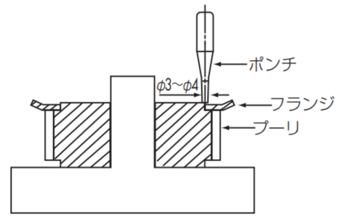
カシメ方式
通常プレスフランジおよび旋削フランジは、下図のようにポンチでカシメて固定します。そのときのカシメ数は次の基準に従ってください。
| 歯先円直径 mm |
30以下 |
30をこえ50以下 |
50をこえ120以下 |
120をこえ250以下 |
| カシメ数 |
4 |
8 |
12 |
16 |
注意
- 平らな盤上にプーリを置き、カシメポンチでフランジをカシメてください。
- ハブと反対側をカシメる時は盤上に置いた円筒状の治具等にハブを挿入し、安定した状態でカシメてください。
 [クリックで拡大]
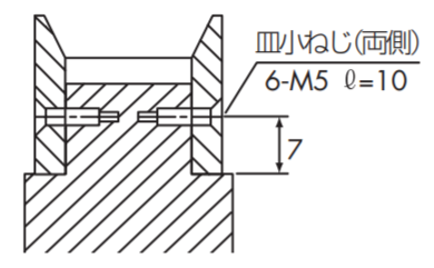
ねじ止め方式
P8M、P14Mの大歯数プーリの旋削フランジは、使い方によってプーリ本体と皿小ねじによって固定する場合があります。下表の皿小ねじ本数は、最小本数です。
| 歯先円直径 mm |
120以下 |
120をこえ250以下 |
250をこえ450以下 |
450をこえ650以下 |
| ねじ本数 |
4 |
6 |
8 |
12 |
 [クリックで拡大]
ローレット方式
旋盤でローレットをかけてカシメる方式もよく使われます。
質問へ戻る
|
| Q4 |
タイミングプーリの選定方法は?(動力からの選定) |
| A4 |
- つばきタイミングベルト伝動カタログ記載簡易選定表を使って設計動力と小プーリ回転速度よりベルトサイズを仮選定してください。
- 同カタログ記載基準伝動容量表でベルト幅および小プーリ歯数を仮選定してください。この際以下のことに注意してください。
- 基準伝動容量の着色部分以外の小プーリ歯数を選んでください。
- 小プーリのピッチ円直径>ベルト幅となるよう小プーリを選んでください。
- 小プーリの軸穴使用可能範囲が使用する軸の直径を満足する事を確認してください。
- 小プーリ歯数と速比より大プーリの歯数を決定してください。また使用軸穴径の確認を行ってください。
質問へ戻る
|
| Q5 |
タイミングプーリの選定方法は?(トルクからの選定) |
| A5 |
- つばきタイミングベルト伝動カタログ記載簡易選定表を使って設計トルクと小プーリ回転速度よりベルトサイズを仮選定してください。
- 同カタログ記載基準伝動トルク表でベルト幅および小プーリ歯数を仮選定してください。この際以下のことに注意してください。
- 基準伝動トルクの着色部分以外の小プーリ歯数を選んでください。
- 小プーリのピッチ円直径>ベルト幅となるよう小プーリを選んでください。
- 小プーリの軸穴使用可能範囲が使用する軸の直径を満足する事を確認してください。
- 小プーリ歯数と速比より大プーリの歯数を決定してください。また使用軸穴径の確認を行ってください。
質問へ戻る
|
| Q6 |
かみ合い歯数が6歯以上必要な理由は? |
| A6 |
金属製のチェーンやギヤと異なりタイミングベルトの歯はナイロン織布で覆われたゴム材ですので、1歯だけでの伝動には適しておらず、複数歯で負荷を受ける必要があります。
タイミングプーリとのかみ合い歯数が6歯未満だと1歯当たりの負荷が大きくなり歯欠けの原因になります。かみ合い歯数が5歯もしくは4歯になってしまう場合は、カタログ記載の「かみ合い補正係数」を加えて選定してください。
駆動プーリの場合、かみ合い歯数が6歯以上でかみ合い角度が120度以上になるようご検討をお願いします。
質問へ戻る
|
| Q7 |
小プーリにて高速回転する条件での注意点は? |
| A7 |
タイミングベルト伝動カタログに記載されている伝動能力表の着色部分の組合せは小プーリが高速で回転する条件になるため、タイミングベルト内部にある心線の屈曲疲労が促進されて寿命が短くなりますので使用を避けてください。
質問へ戻る
|
| Q8 |
サーボモータを使用する場合の注意点は? |
| A8 |
タイミングベルトの周速が速い場合、以下の現象が起こる可能性があります。
- タイミングプーリの速度が33m/s以上になる場合、振れや振動の発生が懸念されますのでバランスをとってください。
- タイミングベルトを選定される際は、サーボモータの特性を考慮してトルクから検討することをお勧めしています。
質問へ戻る
|
| Q9 |
タイミングプーリの材質は? |
| A9 |
プーリ材質は次のものが適しています。
単位:g/cm3
| 材質 |
材質記号 |
単位質量 |
| 機械構造用炭素鋼 |
S45C |
7.85 |
| アルミニウム合金 |
A2017-T4 |
2.8 |
| ステンレス鋼 |
SUS304 |
7.8 |
質問へ戻る
|
| Q10 |
タイミングプーリの表面処理は? |
| A10 |
用途によって各種表面処理が可能ですので検討ください。
| 表面処理の種類 |
効果 |
適用材質 |
| 黒染め |
防錆・装飾 |
炭素鋼 |
| 電気亜鉛めっき |
防錆・装飾 |
炭素鋼 |
| 無電解ニッケルりんめっき |
防錆・装飾 |
炭素鋼 |
| アルマイト |
防錆 |
アルミニウム合金 |
| 硬質アルマイト |
防錆・耐摩耗 |
アルミニウム合金 |
質問へ戻る
|
| Q11 |
バックラッシレス歯形は? |
| A11 |
タイミングベルトのかみ合いは通常バックラッシを設けてありますが、非常に正確な回転を要求されるロボット、電子部品組立機、NC装置、プリンター、プロッターなどのタイミングベルトドライブには、バックラッシを少なくして、回転角度誤差をおさえた特殊なバックラッシレス歯形によるプーリを製作しますので相談ください。
質問へ戻る
|
| Q12 |
カタログ記載品以外の特注品は製作可能か? |
| A12 |
カタログ記載以外の寸法・歯数・材質のプーリも製作可能ですので、当社問合せ窓口もしくは取扱販売店へお問合せください。
質問へ戻る
|
| Q13 |
タイミングプーリが使用可能な雰囲気温度は? |
| A13 |
使用温度範囲 -15℃~80℃(アルミ:0℃~50℃)の通常の環境下でご使用ください。
質問へ戻る
|
| Q14 |
他社品との互換性はあるか? |
| A14 |
つばきPXベルト用プーリは当社独自の歯形なので他社ベルトには使用できません。
つばきタイミングベルトとセットで使用してください。
質問へ戻る
|
| Q15 |
使用前に注意しておくことは? |
| A15 |
注意点をまとめてカタログ「タイミングプーリ」に掲載しています。「取扱説明」のページをご使用前に必ずお読みください。
質問へ戻る
|
| Q16 |
タイミングプーリにタイミングベルトを取付けるときの注意点は? |
| A16 |
タイミングベルトは力を加えてもほとんど伸びません。
タイミングプーリに取付けるときはプーリ軸・アイドラ軸を移動させて取付けてください。
無理にタイミングプーリのガイドフランジを乗り越えさせようとするのは事故の原因になりますので避けてください。
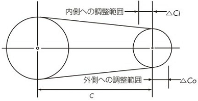
アイドラを使用しない2軸伝動では、軸間距離調整しろを設けておいてください。
■2軸伝動の軸間距離調整しろ
単位:mm
|
ベルト長さ |
種類 |
P2M・P3M・P5M
UP3M・UP5M |
P8M・P14M
UP8M・UP14M |
| △Co |
500以下 |
3 |
3 |
| 500~1000 |
5 |
5 |
| 1001~2000 |
10 |
10 |
| 2000以上 |
15 |
15 |
| △Ci |
共通 |
10 |
15 |
 [クリックで拡大]
質問へ戻る
|
| Q17 |
タイミングベルト&プーリの使用雰囲気で注意することは? |
| A17 |
清浄な雰囲気中で使用してください。
多量の水、油、溶剤がかかる恐れがある、埃が多い雰囲気中で使用される場合はカバーをしてタイミングベルト・プーリを保護してください。空気中に水分、油分が多い雰囲気では「ウルトラPXベルトHA仕様(耐油/耐水仕様)」、水分が多い雰囲気では「PXベルト耐水仕様」が使用可能な場合がありますのでご検討ください。
プーリについては、耐食性・耐薬品性に効果のあるステンレス鋼仕様や、防錆効果のある表面処理仕様が使用可能な場合がありますので、ご検討ください。
質問へ戻る
|
| Q18 |
騒音の種類は? |
| A18 |
一般的には次の通りです。
- ①タイミングベルト歯底部がタイミングプーリ歯先部に衝突するときに発生する衝撃音
- ②タイミングベルトの弦振動音
- ③タイミングベルトの歯がタイミングプーリの歯溝と擦れあいながらかみ合うことにより発生する摩擦音
- ④タイミングベルト側面とタイミングプーリのガイドフランジが擦れたときに発生する摩擦音
- ⑤タイミングベルトとタイミングプーリがかみ合った時、タイミングプーリ歯溝の空気が吐出される際に発生する空気吐出し音
質問へ戻る
|
| Q19 |
騒音の対策は? |
| A19 |
- ①取付張力・プーリ回転速度・ベルト長さ・ベルト幅・プーリ歯数などを変更して、タイミングベルトの固有振動数を変化させる。
- ②高強度タイミングベルトに変更してベルト幅を狭くする
- ③ベルト幅を狭くして多列掛けに変更する。
- ④タイミングプーリのアライメントを調整してタイミングベルトがガイドフランジに接触しないようにする
質問へ戻る
|
| Q20 |
RoHS指令に対応しているか? |
| A20 |
質問へ戻る
|
| Q21 |
タイミングプーリの価格・納期は? |
| A21 |
当社商品はすべて代理店を通じての販売としておりますので、価格・納期については御社にてお付き合いがある当社商品取扱店へご照会ください。
質問へ戻る
|
| Q22 |
プーリ外径が小さ過ぎた場合ベルトへの影響は? |
| A22 |
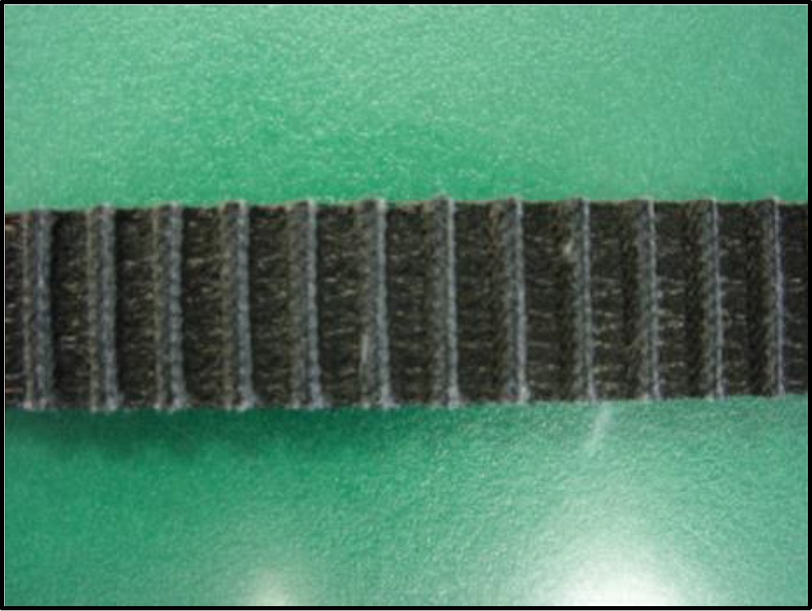
タイミングベルトの早期切断の恐れがあります。
[外観の特長]
ベルト歯に対して平行に切断している。心線も短く揃って切断している。
[推定原因]
- ①保管時や組付時に過度に折り曲げたために心線が破断していた。
- ②プーリ径が小さ過ぎたため心線が破断した。
[対策]
- ①保管時や組付時の取扱いに注意して過度に折り曲げないようにしてください。ピッチの4倍以下の直径に折り曲げないでください。
- ②タイミングプーリ、アイドラの径が適切か確認して、小さすぎる場合は適正な径のものに変更してください。タイミングプーリの径は伝動能力表で、アイドラの径は下の表で確認してください。
■アイドラは次のような場合に使用します。
- 軸受けが固定で取付張力の調整用とする場合
- 速比が大きく、小プーリのかみ合い歯数を大きくする場合
- 駆動、従動プーリでベルトガイドができない場合
■アイドラ使用上の注意
- アイドラは固定式とし、原則としてゆるみ側で使用してください。
- アイドラのアライメントが悪いと、アイドラによってベルトがプーリから外れますのでご注意ください。
- アイドラの直径は下記により決めてください。
- 内側アイドラ......下表の最小プーリ歯数以上のタイミングプーリとします。
- 外側アイドラ......下表のプーリのピッチ円直径の1.2倍以上でクラウンのない平プーリとします。
■アイドラ選定時の最小プーリ歯数
| 種類 |
回転速度 r/min |
| 900以下 |
900をこえ
1200以下 |
1200をこえ
1800以下 |
1800をこえ
3600以下 |
| P2M |
16 |
16 |
18 |
20 |
| P3M・UP3M |
14 |
14 |
16 |
18 |
| P5M・UP5M |
18 |
20 |
24 |
28 |
| P8M・UP8M |
24 |
26 |
26 |
28 |
| P14M・UP14M |
28 |
28 |
28 |
34 |
注)3600r/minをこえる場合は基準伝動容量表を参照ください。

内側アイドラ

外側アイドラ
タイミングベルト背面のゴムの亀裂が起こる恐れがあります。
[外観の特長]
- タイミングベルト背面に歯と平行に亀裂が入っている。
[推定原因]
- ①使用しているタイミングプーリもしくはアイドラ径が小さすぎる。
- ②使用雰囲気温度が高温もしくは低温すぎる。
- ①タイミングプーリ、アイドラの径が適切か確認して、小さすぎる場合は適正な径のものに変更してください。
(タイミングプーリの径は伝動能力表で、アイドラの径は下の表で確認してください。)
■アイドラは次のような場合に使用します。
- 軸受けが固定で取付張力の調整用とする場合
- 速比が大きく、小プーリのかみ合い歯数を大きくする場合
- 駆動、従動プーリでベルトガイドができない場合
■アイドラ使用上の注意
- アイドラは固定式とし、原則としてゆるみ側で使用してください。
- アイドラのアライメントが悪いと、アイドラによってベルトがプーリから外れますのでご注意ください。
- アイドラの直径は下記により決めてください。
- 内側アイドラ......下表の最小プーリ歯数以上のタイミングプーリとします。
- 外側アイドラ......下表のプーリのピッチ円直径の1.2倍以上でクラウンのない平プーリとします。
■アイドラ選定時の最小プーリ歯数
| 種類 |
回転速度 r/min |
| 900以下 |
900をこえ
1200以下 |
1200をこえ
1800以下 |
1800をこえ
3600以下 |
| P2M |
16 |
16 |
18 |
20 |
| P3M・UP3M |
14 |
14 |
16 |
18 |
| P5M・UP5M |
18 |
20 |
24 |
28 |
| P8M・UP8M |
24 |
26 |
26 |
28 |
| P14M・UP14M |
28 |
28 |
28 |
34 |
注)3600r/minをこえる場合は基準伝動容量表を参照ください。
内側アイドラ
外側アイドラ
- ②雰囲気温度をタイミングベルトが使用可能な-15℃~80℃に改善する。
質問へ戻る
|
| Q23 |
タイミングプーリの歯部の摩耗は? |
| A23 |
[外観の特長]
- タイミングベルトとのかみ合い部分が摩耗していて、かみ合っていない部分と段差ができている。
- 歯面が荒れている。
[推定原因]
- ①タイミングプーリの材質が不適切。
- ②粉塵がある雰囲気で使用していて、タイミングベルト・プーリに摩耗性がある粉塵が付着した状態で運転していた。
- ③タイミングベルトの取付張力が高すぎた。
[対策]
- ①硬度の高い材料に変更する、歯面硬化あるいは表面処理を施して耐摩耗性を向上させてください。
- ②使用雰囲気を改善する、もしくは粉塵が付着しないようなカバーを設置してください。
- ③適正な取付張力に調整してください。
質問へ戻る
|
| Q24 |
タイミングプーリの歯部の摩耗によるベルトへの影響は? |
| A24 |
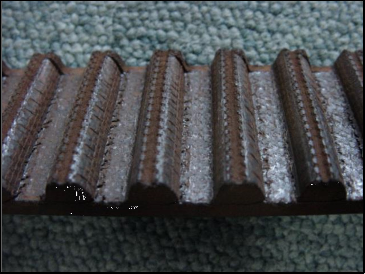
[外観の特長]
- 歯布の毛羽立ち、白っぽく変色、布目が不明瞭になるなどしている。
- 歯布が摩耗してなくなり、ゴムが露出している。
- ベルト歯がやせ細る。
- ベルト歯底の歯布が摩耗してしてなくなり、心線が露出している。
[クリックで拡大]
[クリックで拡大]
[推定原因]
- ① 過負荷(オーバーロード)の発生。
- ② 取付張力過大。
- ③ 取付張力不足。
- ④ タイミングベルトの能力不足。
- ⑤ タイミングプーリの歯形もしくは歯部の寸法不良。
- ⑥ 粉塵雰囲気での使用。
[対策]
- ① 原動機の仕様、被動機の慣性、使用条件を確認してオーバーロードの原因を取り除く、あるいはタイミングベルト・プーリをサイズアップしてください。
- ② ③ 適正な取付張力に調整してください。
- ④ 使用条件を確認して最適なサイズのタイミングベルト・プーリを選定してください。
- ⑤ 正しい歯形・寸法のタイミングプーリと交換してください。
- ⑥ 雰囲気の改善、カバーの設置などでタイミングベルト・プーリに粉塵が付着しないようにしてください。
質問へ戻る
|
| Q25 |
タイミングベルトとのかみ合い歯数不足によるベルトへの影響は? |
| A25 |
タイミングベルトの歯飛びが起こる恐れがあります。
[推定原因]
- ① 過負荷(ショックロード)の発生。
- ② 取付張力不足。
- ③ タイミングプーリとのかみ合い歯数の不足。
- ④ 架台の剛性不足。
[対策]
- ① ショックロードの原因を取り除く、または衝撃緩和機構を設ける。あるいはタイミングベルトをサイズアップしてください。
- ② 適正な取付張力に調整してください。
- ③ タイミングプーリの歯数を増やす、あるいはアイドラを設けてかみ合い歯数を増やしてください。
- ④ 架台の剛性をあげてください。
質問へ戻る
|
| Q26 |
タイミングプーリの整列不良及びガイドフランジ変形によるベルトへの影響は? |
| A26 |
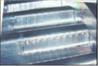
タイミングベルト側面のムシレおよび摩耗
[外観の特長]
- 側面の角がとれて丸みを帯びている。
- 側面のゴムがむしりとられたような状態になっている。
- 心線がほつれて露出している。
[推定原因]
- ①軸の平行度不良。
- ②タイミングプーリの整列不良。
- ③架台の剛性不足。
- ④タイミングプーリのガイドフランジの変形。
[対策]
- ①軸の平行度を正しく調整してください。
- ②タイミングプーリを正しい位置に調整してください。
■プーリのアライメント
タイミングベルトは、プーリのアライメントが正しい場合でもプーリの中央で回転せず、どちらかに片寄る性質があります。
その力は非常に弱いものですが、プーリのアライメントが悪いと、ベルトはプーリフランジに強く押し付けられ、損傷、切断します。
したがってプーリアライメントは下表の許容差内に調整してください。
■プーリのアライメント許容差
| ベルトサイズ |
全品種 |
| ベルト幅 mm |
30以下 |
30~50 |
50~100 |
100以上 |
| 許容平行度 |
5/1000以下 |
4/1000以下 |
3/1000以下 |
2/1000以下 |
| θ分 |
17以下 |
13以下 |
10以下 |
6以下 |
[クリックで拡大]
■プーリ調整方法
図のように基準となるプーリにストレートエッジをあて、他のプーリをストレートエッジ全面に接触させること(ε=0とする)によりプーリを正しい位置に並べることができます。
また図のδを限度以下とすることにより軸の平行度を同時に出すことができます。
[クリックで拡大]
- ③架台の剛性をアップさせてください。
- ④新品に交換してください。
質問へ戻る
|