技術資料 ドライブチェーン ローラチェーンの選定
用途別の選定法
1. 用途別選定法の概要
|
用途 選定の要点 選定法 |
-10℃~60℃の普通雰囲気に おける使用可能な連結部品 |
|||||
|---|---|---|---|---|---|---|
| 継手リンク形式 | オフセット リンク形式 |
|||||
| M形 | F形 | 2ピッチ | 1ピッチ | |||
|
巻掛け伝動 始動頻度6回/日未満 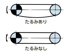
伝動能力表による選定 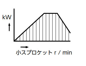
一般選定法 |
RS | ○ | ○ | ○ | □ | |
| BS/DIN | ○ | ● | □ | □ | ||
| LMD | ○ | ● | - | □ | ||
| LMDNP | ○ | - | - | □ | ||
| LMDX | ○ | - | - | - | ||
| LMDS | ○ | - | - | - | ||
| LMDKF | ○ | ● | - | □ | ||
| LMDKT | ○ | ● | - | □ | ||
| LM | ○ | - | - | □ | ||
| SUP | ○ | ● | - | - | ||
| HT | ○ | ○ | - | - | ||
| SNS | ○ | ● | ○ | □ | ||
|
巻掛け伝動 始動頻度6回/日以上
最大許容張力による選定 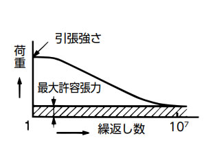
許容張力選定法 吊下げ駆動 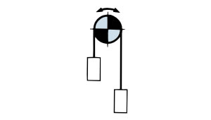
最大許容張力による選定 継手リンクは、F形継手リンクまたは、エンドボルト用専用継手リンクをご使用ください。 吊下げ駆動の例 台車けん引 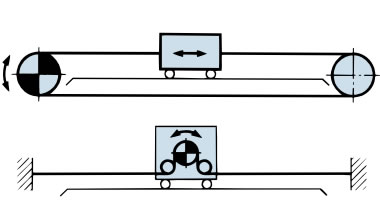
最大許容張力による選定 台車けん引の例 |
RS | ○ | ○ | ○ | △ | |
| BS/DIN | ○ | ○ | △ | △ | ||
| SUP | ○ | ○ | - | - | ||
| HT | ○ | ○ | - | - | ||
| SUPH | ○ | ● | - | - | ||
| USN | - | ● | - | - | ||
| NP | ○ | ○ | - | △ | ||
| NEP(APP) | ○ | ○ | - | △ | ||
| SS,HS | ○ | - | - | ○ | ||
| PC | ○ | - | - | - | ||
| PCSY | ○ | - | - | - | ||
| NS | ○ | - | - | ○ | ||
| TI | ○ | - | - | ○ | ||
| KT | ○ | ○ | - | △ | ||
| CU | ○ | ○ | - | - | ||
| CUSS | ○ | - | - | - | ||
|
チェーン式ピンギヤ駆動 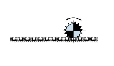
最大許容張力による選定 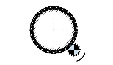
チェーン式ピンギヤ駆動選定法 |
RS アタッチ メント付 |
○ | - | - | - | |
表の記号 ○:使用可能です。 □:伝動能力の低下を見込んでください。 △:強度低下を見込んでください。 -:対象品はありません。 ●:特形製作品。
その他の選定
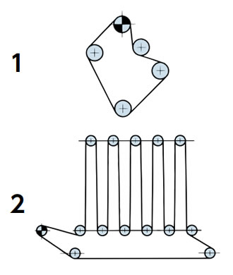
ロール駆動
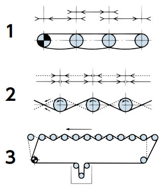
多軸駆動
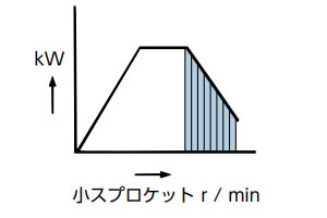
高速駆動
伝動能力表の頂点より右側
(斜線の部分)
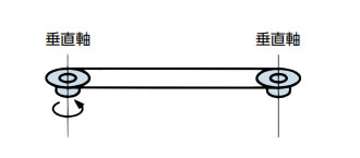
軸が垂直になっている駆動
ローラチェーンの選定に必要な条件の確認
- 1) 使用機械
- 2) 衝撃の種類
- 3) 原動機の種類
- 4) 原動機の定格動力
- 5) 高速軸の軸穴径と回転速度
- 6) 低速軸の軸穴径と回転速度
- 7) 軸間距離
チェーンの選定に必要な原動機特性の確認
許容張力選定法、ピンギヤ駆動選定法では次の原動機特性をご確認ください。
- 1) 原動機の慣性モーメント
- 2) 原動機の定格トルク、または原動機軸回転速度
- 3) 原動機の始動トルク
- 4) 原動機の最大(停動)トルク
- 5) 原動機のブレーキトルク
⚠ 選定でのご注意
ローラチェーンの選定の各項は、ローラチェーンの品種・サイズの選定方法に限っています。腐食、経年などを含む環境による劣化は考慮していません。
ローラチェーンの選定に関して法や指針による規制があるときは、それによる選定と、当社指定の方法による選定の両方を行い、余裕のある方のチェーンを選定してください。付属する機器・例えば安全装置・潤滑装置などについては、別に考慮して選んでください。
