技術資料 ドライブチェーン ローラチェーンの選定
5. 一般選定法
巻掛け伝動(正逆)連続回転伝動
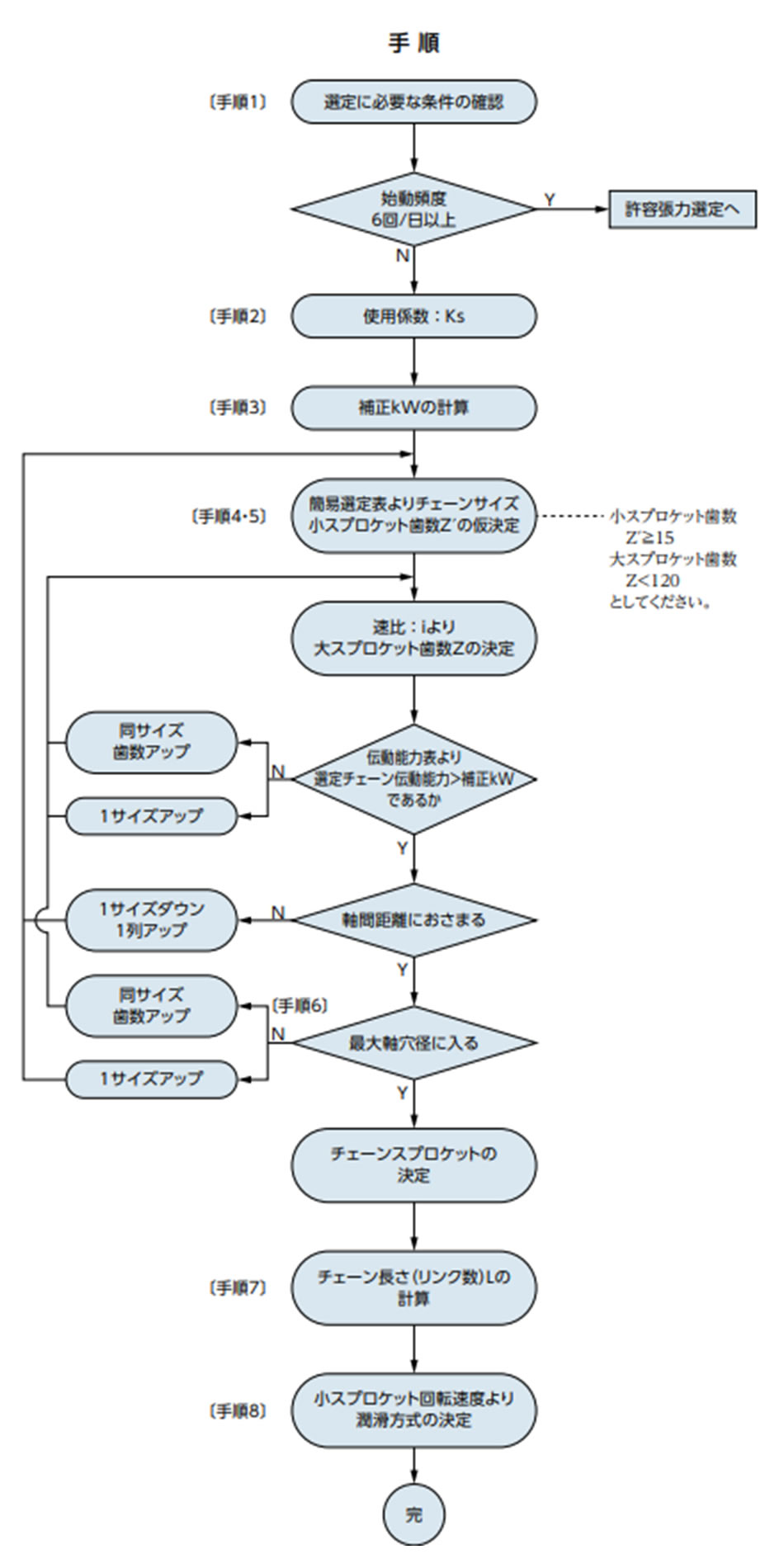
手順4・5 チェーンと小スプロケット歯数の選定
簡易選定図(こちら)、または伝動能力表を使って、高速軸の回転速度と伝動kWを満足するチェーンと小スプロケットの歯数を求めます。
このとき、所要の伝動能力を持つ最小ピッチのチェーンを選びます。
なお、1列チェーンで能力不足のときは、多列チェーンを選んでください。また、使用場所に制限があり、軸間距離を短く、できるだけ
スプロケット外径を小さくするときは、ピッチの小さい多列ローラ
チェーンをご使用ください。
手順6 大スプロケット歯数の選定
小スプロケットの歯数が確定すれば、これに速比を乗じて大スプロケットの歯数を決めます。
小スプロケットの歯数は15歯以上が適当ですが、そのため大スプロケットの歯数が120歯を超えるのは好ましくありません。
そのときは、小スプロケットの歯数を減らしますが、その場合も13歯以上のご使用を推奨します。
手順7 奇数リンクのとき
奇数リンクとなる場合は、オフセットリンクをなるべく使用せずに軸間距離を変えて偶数リンクにします。
RSローラチェーンの1ピッチ形オフセットリンクやスーパチェーンの4ピッチ形オフセットリンクを使用するときは、各伝動能力表の注記に合わせて伝動能力の低下を見込んでください。
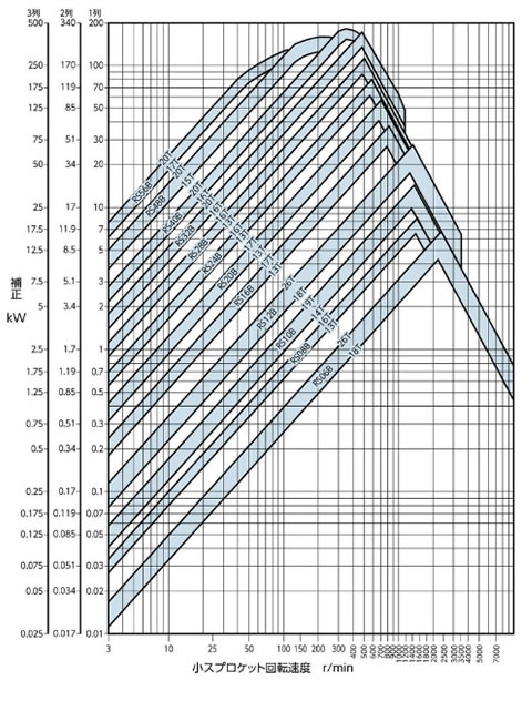
簡易選定図
・図の見方......(図2)
(例)補正 kW = 7kW、1列チェーンの場合
- 1. 小スプロケット回転速度100r/minの場合
補正kW = 7kW(縦軸)と回転速度(横軸)を見ますと、チェーンはRS80、スプロケットは18Tより小、13Tより大ですから、交点の位置より15T(歯数15)前後が使用できると判断します。 - 2. 小スプロケット回転速度200r/minの場合
前例と同様にすれば、RS60-18Tより小、RS60-13Tより大と判断します。以上のようにしてこの表で概略の選定を行ってからチェーン番号別の伝動能力表によって確認します。 - 3. 1ピッチ形オフセットリンクやスーパチェーンの4ピッチ形オフセットリンクを使用するときには、各伝動能力表の注記に従って伝動能力の低下を見込みます。
図2 RSローラチェーン簡易選定図
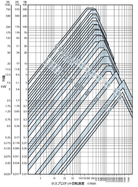
図3 強力チェーンRS-HT簡易選定図
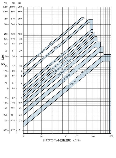
図4 スーパチェーンRS-SUP簡易選定図
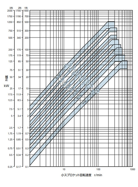
図5 RSローラチェーンBS/DIN規格簡易選定図
簡易選定図
・図の見方......(図2)
(例)補正 kW = 7kW、1列チェーンの場合
- 1. 小スプロケット回転速度100r/minの場合
補正kW = 7kW(縦軸)と回転速度(横軸)を見ますと、チェーンはRS80、スプロケットは18Tより小、13Tより大ですから、交点の位置より15T(歯数15)前後が使用できると判断します。 - 2. 小スプロケット回転速度200r/minの場合
前例と同様にすれば、RS60-18Tより小、RS60-13Tより大と判断します。以上のようにしてこの表で概略の選定を行ってからチェーン番号別の伝動能力表によって確認します。 - 3. 1ピッチ形オフセットリンクやスーパチェーンの4ピッチ形オフセットリンクを使用するときには、各伝動能力表の注記に従って伝動能力の低下を見込みます。
図2 RSローラチェーン簡易選定図
図3 強力チェーンRS-HT簡易選定図
図4 スーパチェーンRS-SUP簡易選定図
図5 RSローラチェーンBS/DIN規格簡易選定図
使用係数 Ks
伝動能力は、負荷変動の少ない場合を条件としていますから、負荷変動の大小により、使用係数Ksで伝動kWを補正するものです。
機械の種類、原動機の種類によって、表2に基づき使用係数Ksを決めます。
伝動kWに使用係数を乗じて、補正kWを求めます。
| 衝撃の種類 | 使用機械例 | 原動機の種類 | ||
|---|---|---|---|---|
| モータ タービン |
内燃機関 | |||
| 流体継手 付 |
流体継手 なし |
|||
| 平滑な伝動 | 負荷変動の少ないベルトコンベヤ、チェーンコンベヤ、 遠心ポンプ、遠心ブロア、一般繊維機械、 負荷変動の少ない一般機械 |
1.0 | 1.0 | 1.2 |
| 多少の衝撃を 伴う伝動 |
遠心圧縮機、舶用推進機、多少負荷変動のあるコンベヤ、 自動炉、乾燥機、粉砕機、一般工作機械、コンプレッサ、 一般土建機械、一般製紙機械 |
1.3 | 1.2 | 1.4 |
| 大きな衝撃を 伴う伝動 |
プレス、クラッシャ、土木鉱山機械、振動機械、 石油さく井機、ゴムミキサー、ロール、ロールガング、 逆転あるいは衝撃荷重のかかる一般機械 |
1.5 | 1.4 | 1.7 |
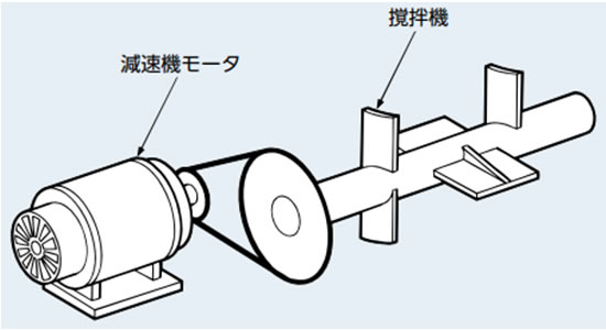
一般選定法による選定例
手順1 選定に必要な条件
- 使用機械:撹拌機
- 衝撃の種類:多少の衝撃を伴う伝動
- 原動機の種類:モータ
- 定格動力:11kW 1800r/min
- 高速軸:軸穴径 Φ45 90r/min
- 低速軸:軸穴径 Φ60 30r/min
- 軸間距離:350mm
- その他:軸間距離方向のスペース 700mm
手順2 使用係数の決定
表2使用係数より、使用係数 Ks = 1.3
| 衝撃の種類 | 使用機械例 | 原動機の種類 | ||
|---|---|---|---|---|
| モータ タービン |
内燃機関 | |||
| 流体継手 付 |
流体継手 なし |
|||
| 平滑な伝動 | 負荷変動の少ないベルトコンベヤ、チェーンコンベヤ、 遠心ポンプ、遠心ブロア、一般繊維機械、 負荷変動の少ない一般機械 |
1.0 | 1.0 | 1.2 |
| 多少の衝撃を 伴う伝動 |
遠心圧縮機、舶用推進機、多少負荷変動のあるコンベヤ、 自動炉、乾燥機、粉砕機、一般工作機械、コンプレッサ、 一般土建機械、一般製紙機械 |
1.3 | 1.2 | 1.4 |
| 大きな衝撃を 伴う伝動 |
プレス、クラッシャ、土木鉱山機械、振動機械、 石油さく井機、ゴムミキサー、ロール、ロールガング、 逆転あるいは衝撃荷重のかかる一般機械 |
1.5 | 1.4 | 1.7 |
手順3 補正kWの決定
補正kW = 11kW × 1.3 = 14.3kW
手順4・5 チェーンとスプロケット歯数の選定
高速軸の回転速度90r/minと補正kW(14.3kW)に基づき、チェーン番号と小スプロケット歯数を求めます。
-
(1)簡易選定図(こちら)、および伝動能力表により、RS100-1の17Tが求まります。
速比は1/3ですから、求める歯数はRS100の17Tと51Tになります。
しかし、スプロケットの外径は、17TがΦ189、51TがΦ534で、要求されるスペースにおさまらないため不適当です。
∵ 189 + 534 > 700 -
(2)そこで多列チェーンを調べますと、
2列ですと、RS80-2の19Tと57Tが求められ、スプロケットの外径はΦ167とΦ476でスペースの制限内です。
このRS80-2の19Tの伝動能力を、RS80の伝動能力表で確認します。
小スプロケット歯数19Tの場合、伝動kWは、50r/minで5.06kW、100r/minで9.44kWですから、この間の表差で比例計算を行います。90r/minの場合の伝動kWを求めると、8.56kWとなります。 -
(3)この8.56kWは、1列チェーンの伝動能力です。採用予定の2列チェーンの伝動能力は、表1の多列係数を乗じます。
8.56kW × 1.7 = 14.6kW×(ドラッグで移動できます)多列係数
多列ローラチェーンの伝動能力は、チェーンの各列にかかる荷重が等分されないため、単列ローラチェーンの列数倍の能力は期待できません。
したがって、多列ローラチェーンの伝動能力は、1列ローラチェーンの伝動能力に多列係数を乗じて求めます。
表1 多列係数 ローラチェーン列数 多列係数 2列 1.7 3列 2.5 4列 3.3 5列 3.9 6列 4.6 - (4)この伝動能力14.6kWは、補正kW(14.3kW)を満足しています。
手順6 軸穴径の確認
寸法表で軸穴径を確認します。RS80-2-19Tの最大軸穴径は、Φ66で所要軸穴径Φ45には使えます。
RS80-2-57Tの最大軸穴径は、Φ89ですからΦ60は使えます。
手順7 軸間距離の決定
軸間距離350mmとすると、(167 + 476)2 < 350 要求するスペースにおさまります。
リンク数は計算式より
2軸巻掛け伝動のとき
- (1)両スプロケットの軸間距離と歯数が決まっている場合
L = Z + Z' 2 + 2C + Z - Z' 6.28 2 C
- (2)チェーンのリンク数と歯数が決まっている場合
C = 1 8 2L - Z - Z' + (2L - Z - Z')2 - 8 9.86 (Z - Z')2求めたLの値の端数(小数点以下)は、たとえ僅かでも切上げて1リンクに数えます。
奇数リンクとなった場合にはオフセットリンクを使用しなければなりませんが、なるべくスプロケットの歯数、または軸間距離を変えて偶数リンクになるようにします。
- L:チェーン長さ(リンク数)
- Z:大スプロケットの歯数
- Z':小スプロケットの歯数
- C:軸間距離をリンク数で表わしたもの
L = 57 + 192 + 2 × 35025.4 + 57 - 196.28235025.4 = 68.2
偶数リンクとするために、小数点以下を切上げて70リンクとします。
手順8 潤滑形式の確認
小スプロケットがRS80-2-19Tで回転速度90r/minですので、伝動能力表により、滴下給油が必要になります。
注)吊下げ用途や台車駆動用途のローラチェーンの選定について
バランスウェイトを使用する時に、モータ容量を小さくし、ブレーキのみ大きくすることが想定されます。
この場合、最大許容張力が示されているものは、許容張力選定法でもチェーンの選定を行い、余裕のある方のローラチェーンを選定ください。
チェーン選定に用いる計算式(こちら)もご参照ください。
