技術資料 クラッチ 選定
選定手順や注意事項等をご覧になりたい方は下記へお進みください。
製品シリーズの絞り込みや仮選定をご希望の方は
こちらをクリックしてください。
選定方法
カムクラッチの用途(オーバランニング・インデキシング・バックストップ)を明確にしてください。用途別に選定法が異なりますので、それぞれの手順に従ってカムクラッチを選定してください。なお、下記の形番の場合は、当社までご連絡ください。
- (1)カムクラッチボックス
- (2)ストッパ付き送り(インデキシング)に使用するクラッチ
1.オーバランニングの場合
- (1)カムクラッチにかかるトルクを下の計算式から算出してください。
トルク計算式
SI単位 T = 60000 × kW 2π × N × S.f(N・m)
{重量単位} T = 974 × kW N × S.f{kgf・m}
T カムクラッチにかかるトルク(N・m) kW カムクラッチ軸の伝達動力(kW) N カムクラッチ軸の回転速度(r/min) S.f 使用係数(下表) 使用係数表
条件 S.f 衝撃トルクなし 1~1.5 やや衝撃トルクあり 1.5~2.5 衝撃トルクあり 2~3 強度の衝撃トルクあり 4~6 - (2)最高空転回転速度
- (3)軸穴径
- (4)取付法
- (5)その他(雰囲気条件、メンテナンスなど)
以上の条件を満足する形番をオーバランニング用クラッチ(上記用途別適合シリーズ一覧表および各掲載ページ参照)の中から選定してください。
| シリーズ | |||||||||||||||||||
|---|---|---|---|---|---|---|---|---|---|---|---|---|---|---|---|---|---|---|---|
| 用途 | MZ MZ-G |
BB | PB | 200 | LD | ML | MG | MI | MX | MI-S | BS | BR BR(P) |
MG-R | MA | MR | カムクラッチ ボックス |
MZ-C | MG-C | |
| 二元駆動 ・ 二速駆動 |
高速空転・高速かみ合い | ○ | ◎ | ○ | |||||||||||||||
| 高速空転・中低速かみ合い | ◎ | ◎ | ◎ | ||||||||||||||||
| 高速空転・低速かみ合い | ◎ | ◎ | ◎ | ◎ | |||||||||||||||
| 中低速空転・中低速かみ合い | ◎ | ○ | ○ | ○ | ○ | ○ | ○ | ◎ | ○ | ||||||||||
| 正転かみ合い、逆転空転 | ◎ | ○ | ○ | ○ | ○ | ○ | ○ | ○ | ◎ | ○ | |||||||||
| フリーホイーリング | ◎ | ○ | ○ | ○ | ○ | ○ | ○ | ◎ | ◎ | ○ | |||||||||
| 手動式 | ○ | ○ | ○ | ◎ | ◎ | ○ | |||||||||||||
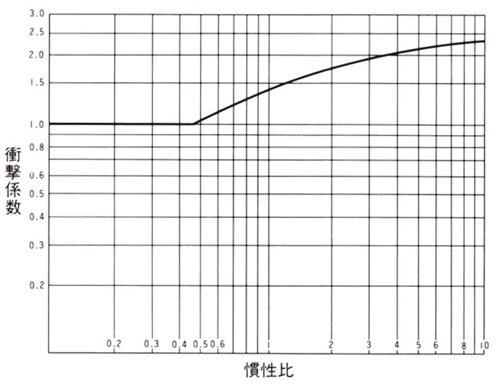
使用係数(S.f)が不明のときは、以下の手順で計算してください。
S.f = 原動機定格トルクの起動 % × 衝撃係数(最大2.5)
衝撃係数は、
慣性比 =
負荷側全慣性モーメント
(クラッチ軸換算)
入力側全慣性モーメント
(クラッチ軸換算)
と下図より求めてください。
衝撃係数
2.インデキシングの場合
2.1 インデキシング送り用カムクラッチ
- (1)カムクラッチにかかるトルクA式、またはB式で求めてください。
注)クランク機構によらないインデキシングの場合には上式は適用できません。 A式
T = I・θ・N2 101750 + TB
T カムクラッチにかかるトルク N・m I 負荷側の全慣性モーメント(カムクラッチ軸換算) kg・m2 θ 1回の送り角度(度)(カムクラッチ軸換算) N 1分間当りインデキシング頻度(回/分) TB 負荷側のブレーキトルク N・m(カムクラッチ軸換算) B式
T = 60000 × P 2π × n ・ ℓ2 ℓ1 × 2.5
T カムクラッチにかかるトルク N・m P 伝達動力 kW n クランク軸の回転速度 r/min ℓ1 クランクの長さ m ℓ2 スイングアームの長さ m 2.5 係数 - (2)最高インデキシング頻度
- (3)送り角度(θ) MI-Sシリーズ以外は90°以下
- (4)N × θ ≦ 20000(高・中低速・送り角度小の場合)
N × θ ≦ 50000(低速・送り角度大の場合) - (5)期待精度
特に高精度の送りを期待する場合はMXシリーズをご使用ください。
あわせて、逆転防止用クラッチやブレーキも高精度のものをご使用ください。 - (6)軸穴径
- (7)取付方法
- (8)その他(寿命、メンテナンスなど)
以上の条件を満足する形番をインデキシング用カムクラッチ(下記用途別適合シリーズ一覧表および各掲載ページ参照)の中から選定してください。
| シリーズ | ||||||||||||||||||
|---|---|---|---|---|---|---|---|---|---|---|---|---|---|---|---|---|---|---|
| 用途 | MZ MZ-G |
BB | PB | 200 | LD | ML | MG | MI | MX | MI-S | BS | BR BR(P) |
MG-R | MA | MR | カムクラッチ ボックス |
MZ-C | MG-C |
| 高速・送り角度:小 | ◎ | |||||||||||||||||
| 中低速・送り角度:小 | ○ | ○ | ○ | ○ | ○ | ○ | ◎ | ○ | ○ | |||||||||
| 低速・送り角度:大 | ◎ | |||||||||||||||||
| 間欠送りの逆転防止 | ○ | ○ | ○ | ○ | ○ | ○ | ◎ | ◎ | ○ | |||||||||
| ストッパ付送り | 当社までご相談ください。 | |||||||||||||||||
| 変速用 | ○ | ○ | ○ | ○ | ○ | ○ | ○ | ◎ | ||||||||||
2.2 間欠送りのバックストップの場合
送り用カムクラッチと同一形番、または1ランク小さい形番を使用してください。
更に、MXシリーズを使用される場合は、下のグラフのそれぞれの曲線の下側の範囲になることを確認してください。
MXシリーズの使用範囲
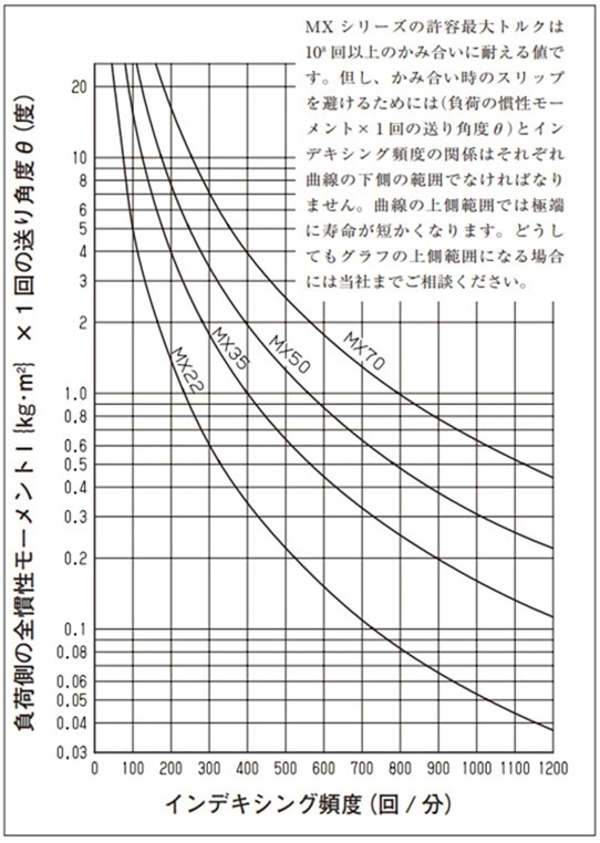
[クリックで拡大]
3.バックストップの場合の選定法
3.1カムクラッチにかかるトルク計算
(1)ベルトコンベヤの逆転防止の場合
[手順1] 無負荷動力(P1)の算出。 P1 = 0.06 × f × W × V × ℓ + ℓ0 367 (kW)
[手順2] 水平負荷動力(P2)の算出。 P2 = f × Qt × ℓ + ℓ0 367 (kW)
[手順3] 垂直負荷動力(P3)の算出。 P3 = h × Qt 367 (kW)
[手順4] 逆転動力(Pr)の算出。 Pr = P3 - 0.7(P1 + P2)(kW)
[手順5] 逆転トルク(T)の算出。 SI単位 T = 60000 × Pr 2π × N × S.f(N・m) {重量単位} T = 974 × Pr N × S.f{kgf・m}
- f = ローラの回転摩擦係数
= 0.03(通常の値) - W = 運搬物以外の運動部の質量 {kg/m}
(ベルト幅により下表の値を使用)ベルト幅 mm 400 450 500 600 750 900 1050 1200 1400 1600 1800 2000 質量 W 22.4 28 30 35.5 53 63 80 90 112 125 150 160 - V = コンベヤ速度 m/min
- Qt = 最大搬送量 t/h
- h = 揚程 m
- ℓ = 頭部と尾部ベルト車間の水平中心距離 m
- ℓ0 = 中心距離修正係数 m
= 49m(通常の値) - N = BSカムクラッチ取付軸の回転速度 r/min
- S.f = 使用係数
(荷重のかかる頻度により下表の値を使用)1日数回程度以下 1.5 1日数回程度以上 2.0
(2)バケットエレベータの逆転防止の場合
[手順1] 逆転トルク(T)の算出。
SI単位 T =
(L + D) × Qt × D × 9800
120 × V
× S.f(N・m)
{重量単位} T =
(L + D) × Qt × D × 1000
120 × V
× S.f{kg・m}
[手順2] 上記逆転トルク(T)が許容最大トルク以内にあるサイズを選んでください。
- 注)1.逆転トルク計算に際して最大搬送量(Qt)はそのコンベヤの能力から考えられる最大の値を採用されることをお奨めします。コンベヤの不意の逆転は、しばしば、そのコンベヤが能力一杯の荷重になった時に起ります。
- 注)2.上記以外のコンベヤの場合は、別途それぞれのコンベヤ固有の計算式により逆転トルクを算出してください。この場合も、そのコンベヤの能力一杯の荷重がかかることを想定して計算してください。
- L = 揚程 m
- D = 頭部コンベヤ鎖車のピッチ円直径 m
- Qt = 最大搬送量 t/h
- V = コンベヤ速度 m/min
- S.f = 使用係数
(荷重のかかる頻度により下表の値を使用)1日数回程度以下 1.5 1日数回程度以上 2.0
- T = 原動機トリップトルク
- kW = モータ容量(kW)
- N = カムクラッチの空転回転速度 r/min
- S = モータの停動トルク %
- Tmax = カタログ許容最大トルク
(3)原動機トリップによる選定
搬送時のトラブル、または結線ミスなどで駆動モータがトリップして停止する可能性がある時は、次式により選定してください。
SI単位 T = 60000 × kW 2π × N × S 100 ≦ Tmax(N・m)
{重量単位} T = 974 × kW N × S 100 ≦ Tmax{kgf・m}
注)上記選定式はBSシリーズ用ですので、他のシリーズの場合は、当社までご相談ください。
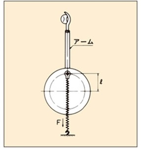
(4)反復衝撃荷重を伴なうバックストップの場合(テニスマシン・ピッチングマシンなど)
必要トルク計算
T = F × ℓ × 3.0
- T:カムクラッチに掛かるトルク(N・m)
- F:バネの最大引張力(N)
- ℓ:偏心量(荷重)
- 3.0:係数
3.2 空転回転速度
3.3 軸穴径
3.4 取付方法
逆転防止トルク一回転速度の早見表
(MG-Rのr/minは連続空転の場合です)
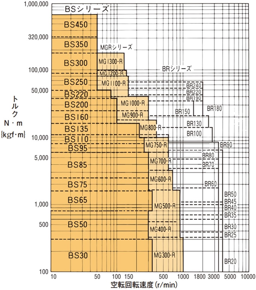
[クリックで拡大]
