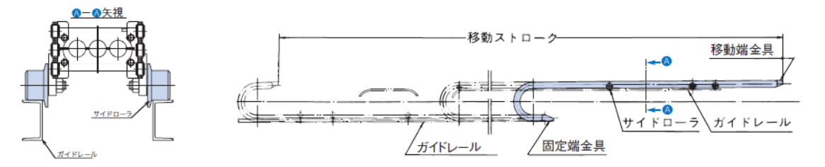
技術資料 ケーブルベヤ - ケーブルベヤの設置例
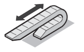
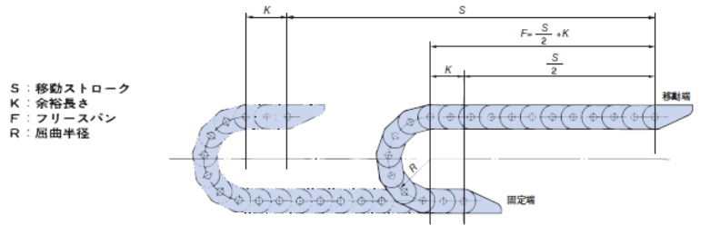
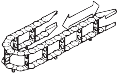
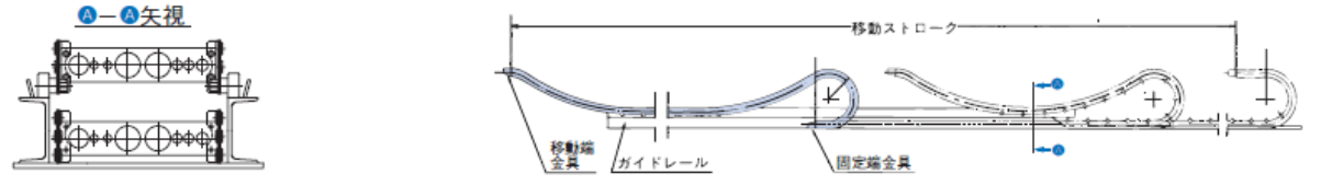
標準設置
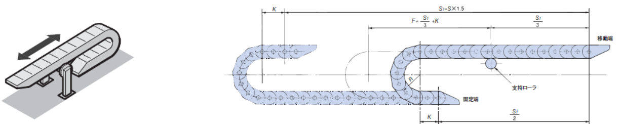
支持ローラ付設置
■適用形式-TK形・TKH形・TKS形・TKP形・TKR形・TKQ形・TKMK形・TKMT形・TKC形(移動速度150m/min以下)
※TKUA形でも適用可能です。ご検討にあたっては当社までお問合せください。
■1ヵ所支持ローラの場合(S1:移動ストローク)-許容移動ストロークは支持ローラが無い場合の1.5倍になります。(TKR形は除く 注)1)
■2ヵ所支持ローラの場合(S2:移動ストローク)-許容移動ストロークは支持ローラが無い場合の2倍になります。(TKR形は除く 注)1)
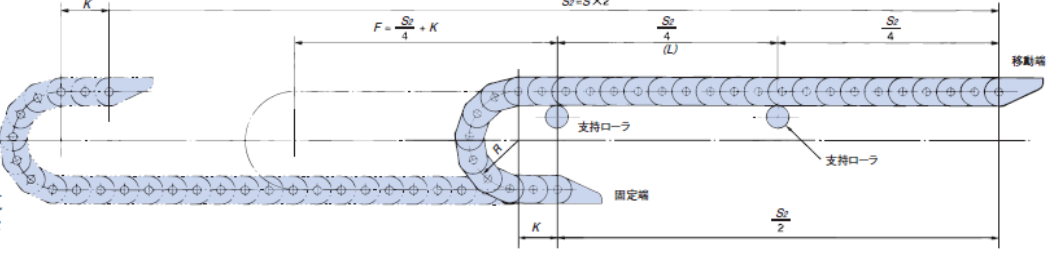
注)TKR形の支持ローラ設置間隔(L)は以下の通りにしてください。
- TKR15H22:L=0.35m以下
- TKR20H28:L=0.7m以下
- TKR26H40:L=0.7m以下
- TKR28H52:L=0.9m以下
注)移動ストロークにより支持ローラが3個以上必要な場合があります。
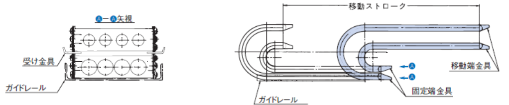
支持プレート付設置
■適用形式-TKC形(移動速度60m/min以下) ※TKC形以外のご検討にあたっては当社までお問合せください。
(S2:移動ストローク)-許容移動ストロークは支持プレートが無い場合の2倍になります。
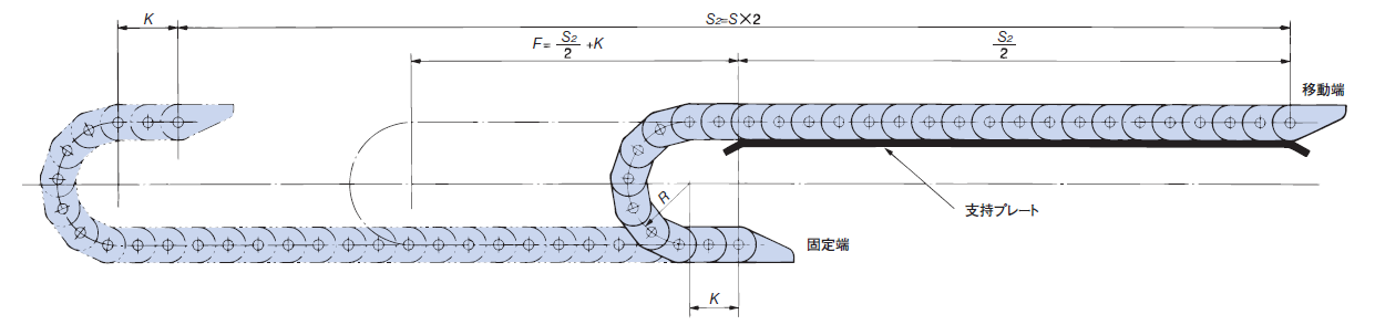
注)支持ローラや支持プレート付のときは、移動端金具を上図に対し天地逆に取付けて使用することはできません。(移動端金具部がローラやプレートと干渉するため)
ロングスパン仕様
■適用形式-TKP形・TKC形・TKMK形・TKMT形
※TKUA形でも適用可能です。ご検討にあたっては当社までお問合せください。
| 特長 | 支持ローラ2カ所設置時の能力線図を越える長いストロークで使用する特殊な設置方法です。 原則として移動端金具は標準と異なる特形です。移動端設置高さは標準と異なります。 |
|---|---|
| 移動ストローク | ロングスパン仕様を参照 |
| 支持物質量 | |
| 移動速度 | |
| ガイド方法 | たわんで走行するケーブルベヤをガイドするための段付レールが必要です。 ケーブルベヤとガイドレールの左右のすきまを標準設置よりも小さくする必要があります。 |
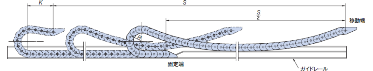
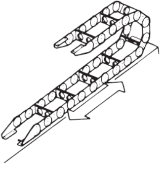
コンビネーション設置
■適用形式-全品種
※ケーブルベヤに無理がかからないよう長さにご注意ください。
| 特長 |
|
|---|---|
| 移動ストローク | 標準設置と同じ(ただし支持ローラは使用できません。) |
| 支持物質量 | 標準設置と同じ |
| 移動速度 | |
| ガイド方法 | |
| 備考 | ケーブルベヤ長さは標準設置の場合より長くなります。傾斜部分を考慮して長さを決定ください。 特に後退時の余裕長さに注意してください。 |
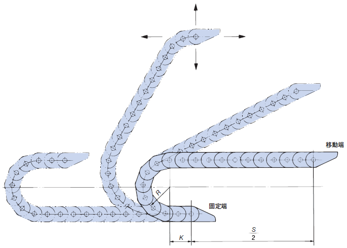
垂直設置
■適用形式-TKS形を除く品種
・ケーブルベヤが垂直方向(上下方向)に移動する場合に使用します。
・ケーブルベヤの揺れ防止、および倒れ防止のために両側にガイドレールが必要です。
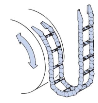
■逆U字形
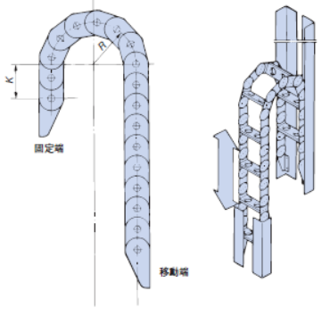
| 特長 |
・直立させて使用する設置方法です。 ・屈曲半径部の頂点にケーブル・ホース質量が集中するため、長ストロークには適しません。 |
|---|---|
| 移動ストローク | 標準設置と同じ |
| 支持物質量 | 当社までご相談ください。 |
| 移動速度 | 標準設置と同じ |
| ガイド方法 |
|
| 備考 |
|
■U字形
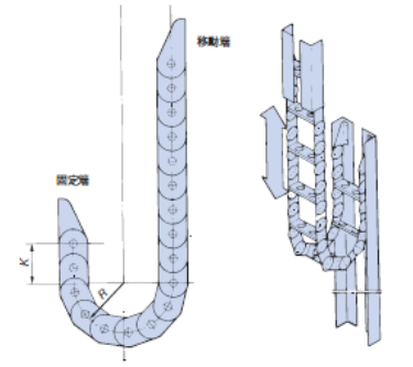
| 特長 |
吊り下げて使用する設置方法です。 引張荷重となるので選定グラフは使用できません。選定目安表を参照してください。 |
|---|---|
| 移動ストローク | 下記一覧表参照 |
| 支持物質量 | |
| 移動速度 | 標準設置と同じ |
| ガイド方法 |
|
| 備考 |
・TK形、TKH形はフリースパン部のふくらみを小さくする特形ピン(水平ピン)を使用します。 ・TK形、TKH形では通常よりもサポータ寸法(高さ)を大きくする場合があります。 |
| サイズ | 最大 移動ストローク m |
最大 支持物質量 kg/m |
最大 移動速度 m/min |
サイズ | 最大 移動ストローク m |
最大 支持物質量 kg/m |
最大 移動速度 m/min |
サイズ | 最大 移動ストローク m |
最大 支持物質量 kg/m |
最大 移動速度 m/min |
||
|---|---|---|---|---|---|---|---|---|---|---|---|---|---|
| TKP13H10 | 6 | 0.6 | 300 | TKR20H28 | 9 | 2 | 300 | TK070 | 8 | 15 | 60 | ||
| TKP18H14 | 7 | 1 | 300 | TKC34H25 | 8.5 | 5 | 300 | TK095 | 7 | 30 | 60 | ||
| TKP18H15 | 7 | 1 | 300 | TKC47H36 | 11 | 8 | 300 | TK130 | 9 | 50 | 60 | ||
| TKP25H15 | 5.5 | 1 | 300 | TKC64H50 | 9 | 16 | 300 | TK180 | 11.5 | 50 | 60 | ||
| TKP35H22 | 5 | 2 | 300 | TKC85H68 | 4.5 | 35 | 300 | TKH250 | 87 | 50 | 60 | ||
| TKP45H25 | 14 | 4 | 300 | TKC91H56 | 9 | 16 | 300 | ||||||
| TKP58H39 | 10 | 6 | 300 | TKC91H80 | 10.5 | 40 | 300 | ||||||
| TKP62H34 | 5 | 7.5 | 300 | TKMK47H28 | 4.5 | 6 | 300 | ||||||
| TKP68H46 | 10 | 6 | 300 | TKMK65H42 | 17 | 15 | 300 | ||||||
| TKP90H50 | 7 | 16 | 300 | TKMK95H58 | 8.5 | 40 | 300 | ||||||
| TKP125H74 | 5.5 | 22 | 300 | TKMK125H72 | 10 | 40 | 300 | ||||||
| TKP91H56 | 9 | 16 | 300 | ||||||||||
| TKP91H80 | 11 | 40 | 300 |
注)固定端が移動ストロークの中央にある場合です。
注)MW仕様を除く(MW仕様でのご採用にあたっては当社までお問合せください)
上面固定形(下移動形)
■適用形式-全品種
| 特長 | 標準設置とは逆に下側が移動する仕様です。 |
|---|---|
| 移動ストローク | 標準設置と同じ |
| 支持物質量 | |
| 移動速度 | |
| ガイド方法 |
|
| 備考 | TK形・TKS形・TKH形はフリースパン部のふくらみを小さくする特形ピン(水平ピン)を使用します。 |
水平仕様
■適用形式-TK形・TKP形・TKC形・TKMK形・TKMT形・TKUA形
| 特長 | ケーブルベヤを横向きにして使用します。 金具取付面が横方向の場合、移動ストロークが長い場合、高さ方向のスペースに制限がある場合に適用します。 |
|---|---|
| 移動ストローク | 下記一覧表参照 |
| 支持物質量 | |
| 移動速度 | |
| ガイド方法 |
|
| 備考 | TK形・TKH形では、ピンはフリースパン部のふくらみを小さくする特形ピン(水平ピン)を使用します。 |
| サイズ | 最大 移動ストローク m |
最大 支持物質量 kg/m |
最大 移動速度 m/min |
サイズ | 最大 移動ストローク m |
最大 支持物質量 kg/m |
最大 移動速度 m/min |
サイズ | 最大 移動ストローク m |
最大 支持物質量 kg/m |
最大 移動速度 m/min |
||
|---|---|---|---|---|---|---|---|---|---|---|---|---|---|
| TKP13H10 | 13 | 0.6 | 60 | TKP91H56 | 45 | 4 | 60 | TKMK47H28 | 18 | 2 | 60 | ||
| TKP18H14 | 15 | 1 | 60 | TKP91H80 | 64 | 8 | 60 | TKMT47H26 | 18 | 2 | 60 | ||
| TKP18H15 | 15 | 1 | 60 | TKC34H25 | 31 | 2 | 60 | TKMK65H42 | 94 | 4 | 60 | ||
| TKP25H15 | 11 | 1 | 60 | TKC47H36 | 43 | 3 | 60 | TKMT65H38 | 94 | 4 | 60 | ||
| TKP35H22 | 11 | 2 | 60 | TKC64H50 | 45 | 4 | 60 | TKMK95H58 | 71 | 6 | 60 | ||
| TKP45H25 | 48 | 2 | 60 | TKC85H68 | 31 | 6 | 60 | TKMT95H54 | 71 | 6 | 60 | ||
| TKP58H39 | 34 | 3 | 60 | TKC91H56 | 45 | 4 | 60 | TKMK125H72 | 73 | 8 | 60 | ||
| TKP62H34 | 21 | 3 | 60 | TKC91H80 | 56 | 8 | 60 | TKMT125H68 | 73 | 8 | 60 | ||
| TKP68H46 | 34 | 3 | 60 | TK070 | 30 | 14 | 30 | ||||||
| TKP90H50 | 42 | 4 | 60 | TK095 | 30 | 18 | 30 | ||||||
| TKP125H74 | 30 | 6 | 60 | TK130 | 60 | 24 | 30 | ||||||
| TK180 | 80 | 26 | 30 | ||||||||||
| TKH250 | 100 | 44 | 30 |
注)MW仕様を除く(MW仕様でのご採用にあたっては当社までお問合せください)
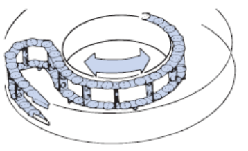
水平旋回形(横旋回形)
■適用形式-TK形・TKP形・TKC形(一部)
※TKUA形でも適用可能です。ご検討にあたっては当社までお問合せください。
| 特長 |
|
|---|---|
| 最大旋回角度 | 約360°(条件によっては、これ以上可能な場合や、これよりも小さくなる場合があります。) |
| 支持物質量 | 水平仕様を参照ください。 |
| 移動速度 | 30m/min以下 |
| ガイド方法 |
|
水平旋回形(横旋回形)
■適用形式-TK形・TKP形
※TKUA形でも適用可能です。ご検討にあたっては当社までお問合せください。
| 特長 |
|
|---|---|
| 最大旋回角度 | 180°~200°(条件によっては、これ以上も可能です。) |
| 支持物質量 | U字形を参照ください。 |
| 移動速度 | 60m/min以下 |
| ガイド方法 |
|
ペンダント形
■適用形式-TK形
| 特長 |
|
|---|---|
| 移動ストローク | フリースパンがカタログ能力内であること。 |
| 支持物質量 | カタログ能力内であること。 |
| 移動速度 | 60m/min以下 |
| ガイド方法 | スプロケットが必要です。 |
| 備考 | サポータ高さを標準よりも大きくすることがあります。 |
コンビネーション設置
■適用形式-TK形(TK070は除く)
| 特長 |
|
|---|---|
| 移動ストローク | ・TK180 50m以下 ・TK130 42m以下 ・TK095 24m以下 ・かつ標準仕様の約4倍以下 |
| 支持物質量 | カタログ能力内であること。 |
| 移動速度 | 30m/min以下 |
| ガイド方法 | ケーブルベヤの高さに沿ってガイドレールが必要です。サイドローラが下へ降りる位置は切欠きます。 |
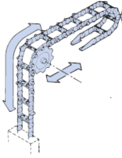
走行ローラ仕様
■適用形式-TK形(TK095、TK130、TK180(R300以上))
| 特長 |
|
|---|---|
| 移動ストローク | カタログ支持ローラ2ヶ所と同等。(それ以上に大きくすることは出来ません) |
| 支持物質量 | カタログ能力内であること。 |
| 移動速度 | 30m/min以下 |
| ガイド方法 | 走行するためのガイドレールが必要です。 |
多段形
■適用形式-TK形・TKH形・TKP形・TKC形・TKMK形・TKMT形・TKUA形
| 特長 |
|
|---|---|
| 移動ストローク | 標準設置と同じただし、通常、支持ローラは使用できません。 |
| 支持物質量 | カタログ能力内であること。 |
| 移動速度 | 標準設置と同じ |
| ガイド方法 |
|
| 備考 | 外周側のケーブルベヤには支持ローラ設置が困難です。 |
