技術資料 ケーブルベヤ - ケーブルベヤの取扱 - 据付・保守、注意点
据付・保守
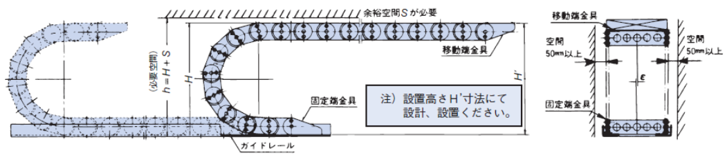
必要空間
ケーブルベヤには本体やケーブル質量によるたわみを補うため、多少のふくらみが付けてありますので、ケーブルベヤの総高さH寸法ではなく、設置高さH'寸法にて設置してください。使用条件や雰囲気に応じてフリースパン部にふくらみやたわみが生じます。上図を参考に必要空間を確保してください。干渉する物がない場合は、一般的には問題ありません。
また使用速度が速くなると振動が生じることがありますので、最大許容速度の70%を越える場合はS寸法を2倍にしてください。
また、使用に伴い、フリースパン部にたわみが生じるため、ケーブルベヤの内周側には空間を設けてください。
| 品種 / サイズ | ε以下 | S | H' |
|---|---|---|---|
| TKP13H10,TKP17H11,TKP18H14/15,TKP25H15 | 3 | 50 | H+(10~30) |
| TKP35H22,TKP45H25,TKUA45H26 | 4 | 100 | |
| 上記以外のTKP形、TKUA55H38,TKUA66H44 | 6 | 100 | |
| TKC形、TKA形 | 6 | 100 | |
| TKMK形、TKMT形 | 6 | 100 | |
| TKR15H22 | 6 | 100 | |
| TKR20H28,TKR26H40,TKR28H52,TKR37H28 | 6 | 100 | H+(30~50) |
| TKQ形 | 6 | 100 | H+(10~30) |
| TK070,TKS070 | 4 | 100 | H+10 |
| TK095,TKS095 | 6 | 100 | |
| TK130 | 8 | 100 | |
| TK180 | 10 | 100 | |
| TKH250 | 15 | 100 | H+30 |

※ケーブルベヤのふくらみを無くしたストレート仕様(特形対応)もあります。特形仕様のページを参照ください。
ケーブルベヤのガイド
ケーブルベヤには、ガイドレールが必要です。下表を参考にして鋼板またはアングルで製作してください。
ケーブルベヤが出入りする部分は、面取りや勾配を付けて円滑に走行できるようにしてください。
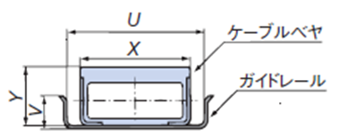
X = ケーブルベヤの外幅、Y = ケーブルベヤの外高さ
| 品種/サイズ | U | V |
|---|---|---|
| TKP13H10,TKP17H11,TKP18H14/15,TKP25H15 | X+10 | Y/2以上 |
| TKP35H22,TKP45H25,TKUA45H26 | X+15 | |
| 上記以外のTKP形, TKUA55H38,TKUA66H44 | X+20 | |
| TKC形 | X+20 | |
| TKMK形、TKMT形 | X+20 | |
| TKR形 | X+20 | |
| TKQ形 | X+20 | |
| TK形、TKS形、TKH形 | X+20 |
給油
ケーブルベヤへの給油は原則として不要ですが、錆やすい雰囲気にTK形、TKS形、TKH形、TKV形を設置する場合は、リンク部をグリースなどで防錆してください。なお、TKI形には潤滑油による給油が必要です。
特殊用途の注意事項
- ■天井走行クレーン横行用など横荷重が作用する場合は、倒れを防止するために支持ローラや横ガイドを設置してください。
- ■マニプレータ、削岩機など外部振動がある場合は、機械からの振動がケーブルベヤに伝わらないように配慮してください。(緩衝装置等)
ロングスパン用レール施工上の注意点
ロングスパン用ガイドレールをお客様にて施工される場合は、下記にご注意ください。取付に簡単便利なロングスパン用ガイドレールも用意しています。
■用語の説明
- 押し勝手:移動端金具を屈曲半径方向に押していく方向に力が作用し、ケーブルベヤが移動していくこと。
- 引き勝手:上記と逆方向にケーブルベヤが移動していくこと(引伸ばしていくこと)。
- 座屈:ケーブルベヤを押し勝手に移動する途中で、ケーブルベヤのレール上を摺動する部分が盛上がること。
- Hレール:固定端金具より前方に設置し、ケーブルベヤが乗上げて摺動する棚部を備えたレール。
- Uレール:固定端金具より後方に設置し、床面のレベルでケーブルベヤを受けるレール。
材質
ガイドレールはスラスト方向への規制をするためのもので、特に摩耗軽減のため材質は滑らかな鋼板製としてください。
防錆処理としてペンキをレールに塗布されますと、摺動によりペンキが剥離し、ケーブルベヤの摩耗の原因となる場合があります。
材質は亜鉛メッキ鋼板あるいはSUS304で施工することを推奨します。
また、屋外で使用する時はSUS304で製作願います。当社製アルミレールは屋外では使用しないでください。
レール設置の精度
- ・水平方向のズレは5m当たりで上下のいずれかに5mm以内とし、全体では一方向に向かって直線的に傾斜していないこと。
- ・横方向のズレは5m当たりで左右のいずれかに3mm以内とし、全体として一方向に向かって直線的に曲がっていないこと。
両端金具設置の精度
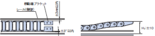

| 移動端側 | 設置高さ | レール全域に対し±10mm以内 |
|---|---|---|
| 幅方向(スラスト方向)のズレ量 | レール側壁に対し全域で±3mm以内 | |
| 平行度 | レール側壁に対し全域で±3°以内 |
| 固定端側 | 設置高さ | Hレールの棚部に対し固定端金具の上面が0~1mm以内 |
|---|---|---|
| 平行度 | レール側壁に対し1°以内 |
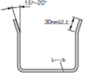
レール上面のテーパ角度
レール上部の開口部は外側に傾斜を付け、ケーブルベヤがレール内にスムーズに入れるように施工します。曲げ角度は15°~20°程度で長さは30mm以上とします。
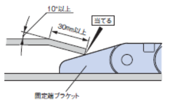
固定端金具とレールの乗移り部の構造
ケーブルベヤの乗移りをスムーズにするためにHレールの乗移り部には傾斜をつけてください。形状は10°以上の傾斜を付け長さは30mm以上とし、レール端面が固定端金具に当たるように設置してください。
当社の専用アルミレールを使用する場合は端面にC2の面取りを加工して設置願います。
レール継目の加工
■Hレール
両側面は引掛かりの無いように継目の端部を外側に曲げてください。
摺動走行する棚部では段差が無く密着していること。また継目に開きを設ける場合は5mm以内とし、C2面取りをし段差が無いこと。
当社の専用アルミレールを使用する場合は摺動走行面にC1の面取りをすること。
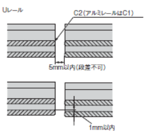
■Uレール
両側面は引掛かりの無いように継目の端部を外側に曲げてください。
底面の段差は1mm以内となるよう設置し、面取りなどの加工は不要ですが、バリや切り口が波打っていない平らな面としてください。
ケーブル・ホースの全長について
ケーブルベヤ本体には連結部(リンクピン、ピン穴間)にクリアランスがあり張力が発生すると基本長さより長くなりますので、ケーブルホースなどの全長は余裕をもった長さでご用意し現物にて調整願います。伸び量は最大で全長の約0.2~0.6%となる場合があるので、長いストロークではご注意ください。
施工の不具合によるトラブル例
- ■側壁の継目に段差がある
ケーブルベヤの屈曲部が段差と干渉し、ケーブルベヤの破損および座屈、摺動による摩耗が発生します。
- ■レール底部の継目に段差がある
Hレールに段差があると、異常摩耗の原因となります。また、Uレールでは大きな段差があると、座屈や部分的な摩耗が発生します。
- ■レールが水平に設置されていない
座屈や走行抵抗の増加が生じる可能性があります。
