技術資料 タイミングベルト・タイミングプーリ 設計資料
プーリと軸の締結
(1)キー止めによる方法
下表の軸穴および軸のはめあい寸法許容差およびキー溝許容差でキー止めする一般的な方法です。
軸穴・キー・タップの加工を規格化し、形番のみで手配できるプーリ フィットボアを参照ください。
- ・アルミプーリの場合は、キー溝面圧80N/mm2以下、かつ一方向回転でご使用ください。
- ・正逆回転で使用される場合はロックプーリをご使用ください。
(2)摩擦力で締結する方法
摩擦式締結具一体形のロックプーリを用意していますのでご参照ください。
ロックプーリの選定は、ロックプーリSタイプおよびロックプーリCタイプを参照ください。
- ・ロックプーリなどの摩擦式締結具は、プーリ本体に強い面圧がかかりますので、アルミロックプーリは高強度アルミ合金を使用しています。標準アルミプーリ(下穴品)を追加工しての摩擦式締結具(パワーロックなど)のご使用は、プーリは破損する場合がありますのでご使用できません。
アルミプーリで、摩擦式締結具をご使用の場合は当社ロックプーリをご使用ください。
軸穴寸法と公差
軸穴および軸のはめあい寸法許容差(JIS B0401)
| 寸法範囲 mm | 軸穴の寸法許容差 | 軸の寸法許容差 | ||
|---|---|---|---|---|
| H7 | H8 | h7 | h8 | |
| 3をこえ6以下 | + 12~0 | + 18~0 | 0~-12 | 0~-18 |
| 6をこえ10以下 | + 15~0 | + 22~0 | 0~-15 | 0~-22 |
| 10をこえ18以下 | + 18~0 | + 27~0 | 0~-18 | 0~-27 |
| 18をこえ30以下 | + 21~0 | + 33~0 | 0~-21 | 0~-33 |
| 30をこえ50以下 | + 25~0 | + 39~0 | 0~-25 | 0~-39 |
| 50をこえ80以下 | + 30~0 | + 46~0 | 0~-30 | 0~-46 |
| 80をこえ120以下 | + 35~0 | + 54~0 | 0~-35 | 0~-54 |
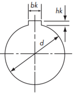
キー溝寸法と公差
フィットボア軸穴完成品の代表的な寸法・公差を参考として下記に示します。
新JISキー Js9
| 軸穴径 | キー寸法 | キー溝深さ d + hk |
溝寸法許容差 bk |
|---|---|---|---|
| 10以上12以下 | 4×4 | d + 1.8 | 4±0.0150 |
| 12をこえ17以下 | 5×5 | d + 2.3 | 5±0.0150 |
| 17をこえ22以下 | 6×6 | d + 2.8 | 6±0.0150 |
| 22をこえ30以下 | 8×7 | d + 3.3 | 8±0.0180 |
| 30をこえ38以下 | 10×8 | d + 3.3 | 10±0.0180 |
| 38をこえ44以下 | 12×8 | d + 3.3 | 12±0.0215 |
| 44をこえ50以下 | 14×9 | d + 3.8 | 14±0.0215 |
| 50をこえ58以下 | 16×10 | d + 4.3 | 16±0.0215 |
| 58をこえ65以下 | 18×11 | d + 4.4 | 18±0.0215 |
| 65をこえ75以下 | 20×12 | d + 4.9 | 20±0.0260 |
| 75をこえ85以下 | 22×14 | d + 5.4 | 22±0.0260 |
| 85をこえ95以下 | 25×14 | d + 5.4 | 25±0.0260 |
旧JISキー E9
| 軸穴径 | キー寸法 | キー溝深さ d + hk |
溝寸法許容差 bk |
|---|---|---|---|
| 10以上13以下 | 4×4 | d + 1.5 | 4 +0.050 |
| 13をこえ20以下 | 5×5 | d + 2.0 | 5 +0.050 |
| 20をこえ30以下 | 7×7 | d + 3.0 | 7 +0.061 |
| 30をこえ40以下 | 10×8 | d + 3.5 | 10 +0.061 |
| 40をこえ50以下 | 12×8 | d + 3.5 | 12 +0.075 |
| 50をこえ60以下 | 15×10 | d + 5.0 | 15 +0.075 |
| 60をこえ70以下 | 18×12 | d + 6.0 | 18 +0.075 |
| 70をこえ80以下 | 20×13 | d + 6.0 | 20 +0.092 |
| 80をこえ95以下 | 24×16 | d + 8.0 | 24 +0.092 |
キー溝加工を希望のときは、寸法および許容差を指示ください。
指示のない場合は上表の許容差にて加工します。
プーリの表面処理
用途によって各種表面処理が可能ですのでご検討ください。
| 表面処理の種類 | 効果 | 適用材質 |
|---|---|---|
| 黒染め | 防錆・装飾 | 機械構造用炭素鋼 |
| 電気亜鉛めっき | 防錆・装飾 | 機械構造用炭素鋼 |
| 無電解ニッケルりんめっき | 防錆・装飾 | 機械構造用炭素鋼 |
| アルマイト | 防錆 | アルミニウム合金 |
| 硬質アルマイト | 防錆・耐摩耗 | アルミニウム合金 |
標準在庫品の追加工
タイミングプーリは歯部外径をチャッキングして軸穴加工していただくのが最も良い方法ですが、BF形またはB形の標準プーリは歯部外径とハブ外径の同心度が正確に加工されていますので、軸穴加工にあたってはハブ外径チャッキングをお奨めします。
またDF形プーリを加工する際はフランジが回りますので、回り止めのためタップ穴に止めねじを入れて加工してください。
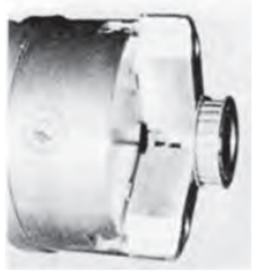
BF形のチャッキング例
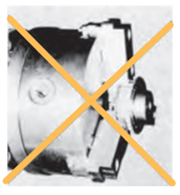
フランジ部のチャッキングは絶対避けてください。
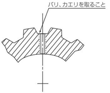
タップ加工
歯底部に加工する場合は、バリ、カエリを十分とってください。バリ、カエリはベルトに損傷を与えますので、ご注意ください。(ハブ付きのプーリはハブへタップ加工してください。)