技術資料 大形コンベヤチェーンスプロケット スマート取替シリーズ 取扱
取付・取外しの前に
注意事項
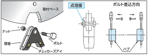
- ・スプロケットまたは替歯の取替作業では重量バランスがくずれ、軸が回転したり、スプロケットや替歯が落下したりするおそれがあります。確実に支持・固定した状態で作業を行ってください。また安全な作業場所と十分な作業人員を確保したうえで作業を進めてください。
- ・リング替歯タイプ・ブロック替歯タイプの取外しで、搬送物の固着や腐食などで致し方なくボルトを焼切るなどの対処を行った場合は、取付ベース座面のきず・付着物などをやすり・グラインダなどで除去してください。ボルトより小さい径の当て金(棒)をボルトに当て、ハンマーで叩くと抜取りやすくなります。
- ・特に重量が大きいサイズのスプロケットや替歯には、吊穴またはアイボルト用タップを設けています。スリングやワイヤなどで確実に固定ください。
- ・軸のスプロケット取付部やスプロケット本体の分割部・取付ベースを十分に清掃してください。きず・腐食・搬送部の固着などがある場合はやすり・グラインダなどで除去し、滑らかに仕上げてください。
取付・取外し手順
1. 分割タイプ
取付手順
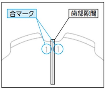
- 1. 分割したスプロケットを軸の取付部で組合せてください。
このとき、歯部にある合マークが一致するように組合せてください。 - 2. 分割されたスプロケットを組合せたとき、ハブ部の取付面に隙間がなく、歯部の取付面に隙間がありますが、噛み合せにおいて機能上、問題はありません。
- 3. ボルトは付属のばね座金を使用し、トルクレンチで確実に締付けてください。
- 4. 軸に取付ける際は分割面同士のずれがないように取付けてください。
付属のばね座金を使用しボルトを均等になるよう締付けてください。
締付トルクは下表の通りです。
| ボルトサイズ | M8 | M10 | M12 | M14 | M16 | M20 | M24 | M30 |
|---|---|---|---|---|---|---|---|---|
| 締付トルク[N・m] | 34 | 68 | 118 | 186 | 289 | 568 | 980 | 1960 |
※スプロケットに付属している専用のボルトをご使用ください。
※適切な締付トルクでご使用すれば一般的な環境において緩みにくい高張力ボルトを使用していますが、
大きな振動を受ける場合など緩みが懸念される場合は、緩み止め防止剤の併用など緩み止めを施してください。
2. リング替歯タイプ
取付手順
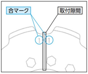
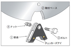
- 1. 替歯は合マークが一致するように取付面に設置し、ボルト・ばね座金・ナットで仮締めしてください。
- 2. 取付隙間が均等になるように調整してください。隙間の目安は1~3mmです。この隙間は、噛み合せにおいて機能上問題はありません。
- 3. 取付けて隣合う替歯の歯底の高さが均等になるように調整ください。
- 4. ボルト・ナットの取付
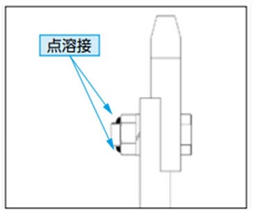
点溶接取付仕様の場合
緩止めの点溶接は全てのナットに施工ください。すべてのナットに緩止めの点溶接を2ヶ所施工ください。スプロケットは振動・腐食・衝撃・腐食雰囲気など厳しい条件下での使用が想定されます。締付トルクは下表の通りです。ボルトサイズ M8 M10 M12 M14 M16 M20 M24 M30 締付トルク[N・m] 34 68 118 186 289 568 980 1960 ※替歯に付属している専用のボルト・ナット・座金をご使用ください。
ハードロックナット取付仕様の場合
ハードロックナットの本締めを行ってください、また均等になるよう締付けてください。
より確実な締付けを行うために、トルクレンチをご使用ください。
その締付トルクは下表の通りです。サイズ 凸ナット(下ナット) 凹ナット(上ナット) 部品構成参考図 締め付けトルク
※単位は[N・m]締め付けトルク
※単位は[N・m]リング替歯 M10 39 18~24 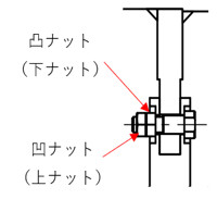
M12 68 27~39 M14 110 40~58 M16 170 70~100 M20 330 120~200 M24 570 160~300 M30 1130 270~440 ※替歯に付属している専用のボルト・ハードロックナット・座金をご使用ください。
ボルトの先端・ハードロックナット・座金・替歯まで、一直線につながるようにマーカで線を引いて下さい。※スプロケットは振動、衝撃、腐食雰囲気等、厳しい環境下での使用が考えられます。
これにより、ボルト及びナットは緩みやすくなることが想定されますので緩み確認のマーカは全ての取付部品について施工してください。
取外手順
- 1. 替歯を取外すときは、点溶接をグラインダなどで除去してください。
- 2. ボルトを抜いて替歯を取外してください。ナットを取り外す際、搬送物の固着やスプロケットの腐食などで取外しできず、致し方なくボルトを焼切るなどの対処を行った場合は、取付面ベース座面のきず・付着物などをやすり・グラインダなどで除去してください。
- ◎点溶接からハードロックナットへ置き換えの場合
- 1. ナットの緩み止めの点溶接をグラインダなどで除去してください。
- 2. 各歯部はボルトとナットで取付けています。
それぞれのナットを緩めて取り外してください、その際歯部が落下しないよう確実に固定してください。
特に重量が大きいサイズは吊穴またはアイボルト用タップを設けていますのでスリングやワイヤを使用するなどして確実に固定してください。 - 3. ボルトを抜いて替歯を取外してください。
- 4. 同様にして残りの替歯を取外してください。
- ※ナットを取外す際、搬送物の固着やスプロケットの腐食等で、ナットを取外しにくい状況が考えられます。
ボルトを焼き切るなどの対処を行い、ボルト、ナットの座面に傷、付着物などが付いた場合は必ずやすり、
グラインダなどで滑らかに仕上げてください。
ボルト、ナットの座面はリング替歯シリーズ スプロケットの構造上重要な要素です。
3. ブロック替歯タイプ
取付手順
- 1. 専用接着剤(付属)を替歯の取付部全体にヘラなどで塗布してください。
- 2. 替歯を取付ベースへ組込む際は、取付ベースの底部と替歯が接触していることを確認してください。
- 3. 接触を確認後、付属のボルト・ナットで締付けてください。
注)バケットエレベータに使用するときはコンベヤの内側から外側へボルトを組込んでください。
- 4. 全てのナットには緩止めの点溶接またはハードロックナットでの締付けを施工してください。
点溶接取付仕様の場合
接触を確認後、付属のボルト・ナットで締付けてください。
バケットエレベータに使用する時はコンベヤ内側から外側へボルトを組込んでください。作業と点検がしやすくなります。
ボルトの締付けには、トルクレンチをご使用下さい。 その締付トルクは下表の通りです。
接触を確認後、付属のボルト・ナットで締付けてください。
バケットエレベータに使用する時はコンベヤ内側から外側へボルトを組込んでください。
作業と点検がしやすくなり、アタッチとの干渉を防げます。
ボルト・ナットの締付けには、トルクレンチをご使用下さい。
締付トルクは下表の通りです。
接触を確認後、付属のボルト・ナットで締付けてください。
バケットエレベータに使用する時はコンベヤ内側から外側へボルトを組込んでください。作業と点検がしやすくなります。
ボルトの締付けには、トルクレンチをご使用下さい。 その締付トルクは下表の通りです。
| ボルトサイズ | M8 | M10 | M12 | M14 | M16 | M20 | M24 | M30 |
|---|---|---|---|---|---|---|---|---|
| 締付トルク[N・m] | 34 | 68 | 118 | 186 | 289 | 568 | 980 | 1960 |
※替歯に付属している専用のボルト・ナットをご使用ください。
ハードロックナット取付仕様の場合接触を確認後、付属のボルト・ナットで締付けてください。
バケットエレベータに使用する時はコンベヤ内側から外側へボルトを組込んでください。
作業と点検がしやすくなり、アタッチとの干渉を防げます。
ボルト・ナットの締付けには、トルクレンチをご使用下さい。
締付トルクは下表の通りです。
| サイズ | 凸ナット(下ナット) | 凹ナット(上ナット) | 部品構成参考図 |
|---|---|---|---|
| 締め付けトルク ※単位は[N・m] |
締め付けトルク ※単位は[N・m] |
リング替歯 | |
| M10 | 39 | 18~24 | |
| M12 | 68 | 27~39 | |
| M14 | 110 | 40~58 | |
| M16 | 170 | 70~100 | |
| M20 | 330 | 120~200 | |
| M24 | 570 | 160~300 | |
| M30 | 1130 | 270~440 |
※替歯に付属している専用の特殊ボルト・ハードロックナットをご使用ください。
5. このままの状態で約24時間放置して、接着剤を乾燥させてください。
取外手順
- 1. 替歯を取外すときは、点溶接をグラインダなどで除去してください。
- 2. ボルトを抜いて替歯を取外してください。ナットを取り外す際、搬送物の固着やスプロケットの腐食などで取外しできず、致し方なくボルトを焼切るなどの対処を行った場合は、取付面ベース座面のきず・付着物などをやすり・グラインダなどで除去してください。
- 3. ボルトを抜いて替歯を取外してください。ボルトを抜いた際に替歯が抜けて落下しないよう注意しながら作業を実施してください。
- 点溶接からハードロックナットへ置き換えの場合
- 1. 替歯はナットの緩止めの点溶接をグラインダなどで除去して、ナットを緩めて取外します。
ナットを緩める前には対象の替歯を緩めた時に落下しないように確実に支持・固定していることを確認し、安全な作業場所と、十分な作業人員を確保したうえで作業を進めてください。 - 2. ナットを取外す際に搬送物の固着やスプロケットの腐食などで取外しできず、仕方なくボルトを焼切るなどの対処を行った場合は、取付ベース座面の傷・付着物などが考えられますので、やすり・グラインダなどで除去してください。
- 3. ボルトを抜いて替歯を取外してください。いきなり替歯が抜けて落下しないように注意しながら作業を実施してください。
チェッカーズアイ® 点検
チェッカーズアイはスプロケットの取替タイミングを一目で判定できるオプションです。詳細はこちらをご参照ください。
チェッカーズアイは下記にしたがい点検ください。
1. 点検手順
- 1. スプロケット側面に付着物がある場合は除去し、チェッカーズアイを確認できるようにしてください。
- 2. 摩耗がチェッカーズアイに接したときが使用限度です。
- ・チェッカーズアイはスプロケット1個につき2ヶ所(目安:0°と180°)の歯に埋込んでいます。
- ・チェッカーズアイの位置は形番により異なります。軸穴加工品の場合、一か所はキー溝部付近の歯部に埋込みます。
2. 注意事項
- ・摩耗がチェッカーズアイに接した後に継続してそのまま使用されると摩耗が急速に促進されます。チェーンの摩耗へも影響を与えますので速やかに取替てください。
- ・摩耗がチェッカーズアイに接する前でも、歯幅の摩耗量が20%を超えたらスプロケットを取替えてください。また、20%を超える前に摩耗が確認されたら、スプロケットの心出しを見直してください。
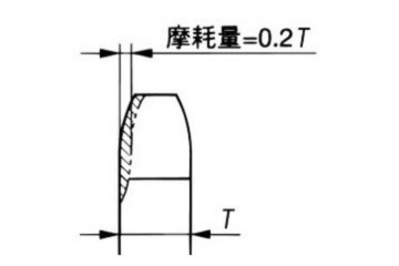
歯の側面の摩耗
