技術資料 トップチェーン 選定
プラローラテーブルの走行レール
注)走行レールについては走行レールの項を参照ください。
2-1. 搬送側走行レール(ST形、RT形)
2-1-1. プラローラテーブル1列使用の場合
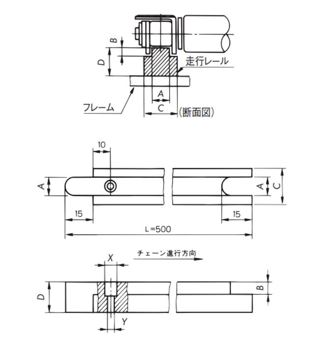
| サイズ | 寸法 | 取付ネジ | 材質 | |||||
|---|---|---|---|---|---|---|---|---|
| A | B | C | D | X:深さ | Y | |||
| ST300 | 4 | 2.7 | 9.5 | 10 | Φ3.2:3 | Φ1.8 | M1.6 なべ小ネジ | Pレール 超高分子量 ポリエチレン |
| RT300 | 1.6 | |||||||
| ST400 | 7 | 3.1 | 12 | 10 | Φ4.0:4 | Φ2.2 | M2 なべ小ネジ | |
| RT400 | 1.7 | |||||||
| ST500 | 8.5 | 3.5 | 15 | 10 | Φ6.0:4 | Φ3.2 | M3 なべ小ネジ | |
| RT500 | 2 | |||||||
| RT600 | 11.7 | 2.6 | 19 | 10 | Φ6.0:4 | Φ3.2 | M3 なべ小ネジ | |
2-1-2. プラローラテーブルST形多列使用の場合
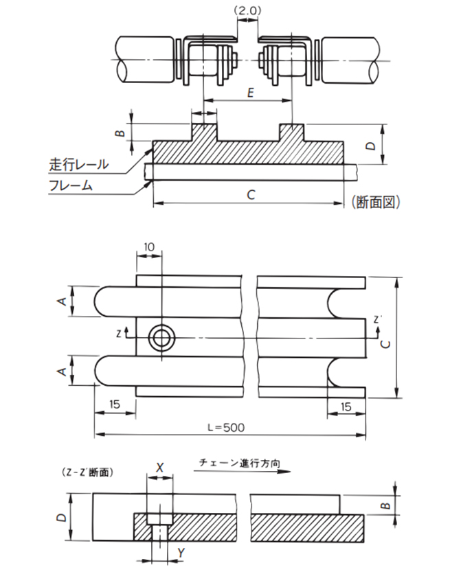
| サイズ | 寸法 | 取付ネジ | 材質 | ||||||
|---|---|---|---|---|---|---|---|---|---|
| A | B | C | D | E | X:深さ | Y | |||
| ST300 | 4.0 | 2.7 | 26 | 10 | 16.5 | Φ8:5 | Φ4.2 | M4 なべ小ネジ | Pレール 超高分子量 ポリエチレン |
| ST400 | 7.0 | 3.1 | 36.5 | 10 | 24.5 | ||||
| ST500 | 8.5 | 3.5 | 43.5 | 10 | 28.5 | ||||
2-1-3. 走行レール取付方法
- ・走行レールはフレームにベタ受けとしてください。
- ・走行レールは超高分子量ポリエチレンを使用しますので温度、湿度による伸びが大きいため、フレームへの固定は端部1ヵ所ネジ止めとし、接合部は5mm程度のスキマをあけてください。
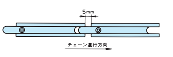
- ・走行レールの両サイドをスチール、またはステンレスの角材などでガイドしてください。
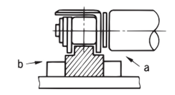
注)
- a部:プラローラテーブル内のプラローラ部と干渉しないこと。
- b部:隣接するトップチェーンなどと干渉しないこと。
※線膨張係数
- プラレール(Pレール)、PLFレール:20×10-5/℃
- Mレール:9×10⁻⁵/℃
注)
- 1. プラレールの使用温度範囲
プラレール(Pレール)、PLFレール:-20~60℃
Mレール:-20~80℃ - 2. 蒸気の掛かる条件ではプラレールを使用しないでください。
2-2. 戻り側走行レール
2-2-1. ST形、RT形共通
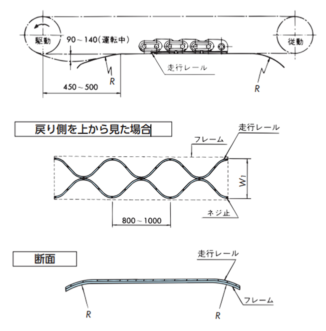
- ・走行レールの両端部は下表の曲げRとしてください。
サイズ 曲げR ST300, RT300, RT400, RT500, RT600 200以上 ST400 250以上 ST500 300以上 - ・運転中に駆動スプロケットの下に上図のようにチェーンにたるみが出るようにしてください。
- ・走行レールは特定の列のプラローラ部が摩耗しないような形状にします。
- ・走行レール幅W1はC1(有効幅)-10とします。
- ・走行レールは超高分子量ポリエチレンをご使用ください。
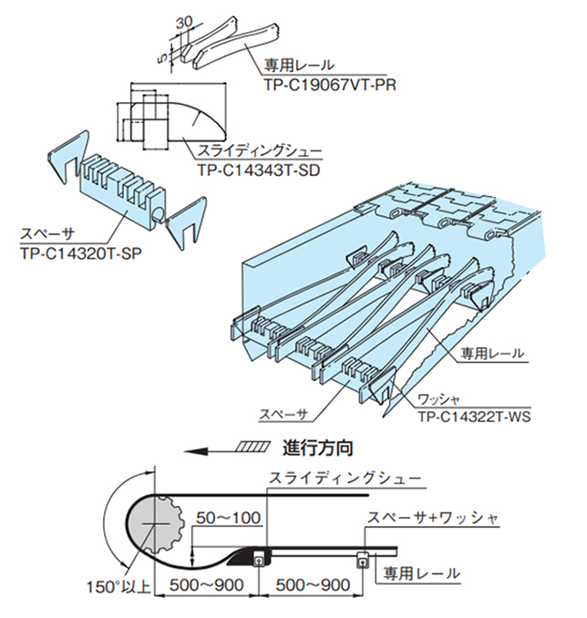
2-2-2. トップチェーンアクセサリを使用
- (1)スライディングシュー(TP-C14343T-SD)、スペーサ(TP-C14320T-SP)を使用
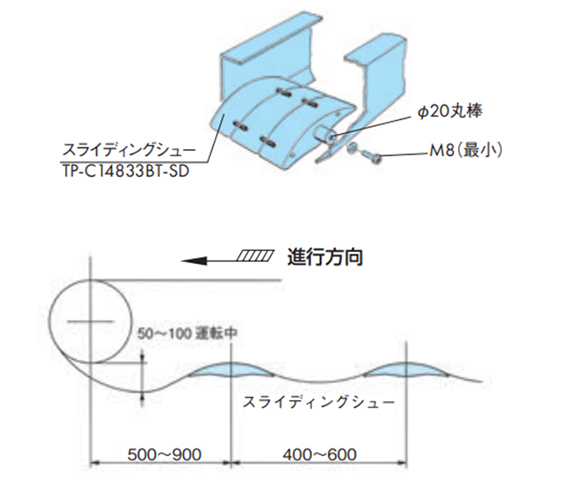
適用チェーン...プラローラテーブルRT形 - (2)スライディングシュー(TP-C14833BT-SD)を使用
適用チェーン...プラローラテーブルST300、ST400、RT形