技術資料 トップチェーン 選定
このページでは以下の項目について紹介しています。
(各項目をクリックすると本文にスクロールできます。)
- 2-1. レールの配置
- 2-2. ガイドクリアランス
- 2-3. 走行レールの取付例(常温雰囲気の場合)
- 2-4. コンベヤのレイアウト
- 2-5. WT0700シリーズ両端ノーズバーの取付例
- 2-6. WT1500シリーズおよびBTN5と両端ノーズバーの取付例
- 2-7. WT2520シリーズの正逆底部駆動のレイアウト
- 2-8. ノーズバーの突合せレイアウト
- 2-9. BTC4-M形の突合せレイアウト
- 2-10. WT2520シリーズの突合せレイアウト
- 2-11. 直交搬送レイアウト
- 2-12. WT1500とWT1505Gの直交搬送
- 2-13. 傾斜コンベヤのテークアップ
- 2-14. フライトタイプチェーンの戻り側
- 2-15. 浮上がり防止アタッチメント(タブ)の特殊編成
- 2-16. トランスファプレートの設置
プラスチックモジュラーチェーン(幅広) コンベヤ設計資料
2-1. レールの配置
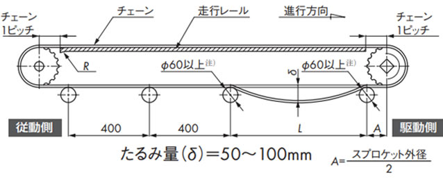
レールの配置は設置スペースなどにより異なりますが一例を下図に示します。(高荷重レイアウト)
注)
- 1. 駆動スプロケット部の走行レールおよびフレーム端面は、面取りを施し干渉しないようにしてください。
- 2. WT1907、WT3827、WT5707はΦ80以上。
- 3. WT0705-W形、WT1515-W形、WT1516-W形、WT0705-M形、WT1515G-M形、BTC4-M形はΦ20以上。
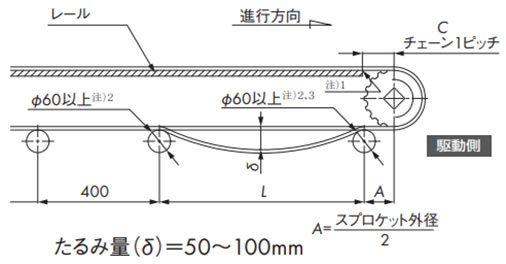
2-1-1. チェーンのたるみ量
駆動スプロケット下の戻り側チェーンを受けるリターンローラの間隔Lは下記表5を参照し、リターンローラ間のチェーンのたるみ量は50~100mmとしてください。このたるみにより歯飛びを防止しています。この範囲以外では歯飛びする可能性があります。
表5. リターンローラ間隔 L
| チェーン形式 | リターンローラ間隔 L | |
|---|---|---|
| 張力負荷率(F1) | ||
| 50%以下の時 | 50%を超える時 | |
| WT0405, WT0705 | 400 ~ 600 | |
| BT6, BT8 | 500 ~ 700 | 800 ~ 1000 |
| WT2250, WT2515, WT2525, WT2525VG | 600 ~ 900 | |
| WT1500, 2500, 3000, 3800 | 450 ~ 500 | |
| WT3109, BTH16 | 750 ~ 1000 | |
WT1907、WT3827、WT3835、WT5707の場合
| 搬送条件 | ローラ間隔 L |
|---|---|
| 機長12m未満、搬送物質量75kg/m2以下の場合 | 600 ~ 900 |
| 機長20m未満、搬送物質量100kg/m2以下の場合 | 750 ~ 900 |
| 機長20m未満、搬送物質量100kg/m2を超える場合 | 1200 ~ 1500 |
注)
- 1. 固定幅タイプはプラトップチェーンと同様に設計ください。
- 2. パストライザーなど特殊コンベヤについては当社までお問合せください。
- 3. 両端ノーズバーの取付けを参照ください。
WT0705-W形・WT1515/6-W形・WT0705-M形・WT1515G-M形・BTC4-M形の場合
| リターンローラ | 推奨チェーン幅 | リターンローラ軸間距離 |
|---|---|---|
| TP-RR20650 | 300mm以下 | 400mm |
| TP-RR30850 | 500mm以下 | 400 ~ 600mm |
| TP-RR41050 | 600mm以下 |
2-1-2. かみ合い角度
駆動スプロケットとチェーンの「かみ合い角度」は180°注)以上にしてください。角度が小さい場合、歯飛びする可能性があります。
注)底部駆動の「かみ合い角度」は200°以上です。
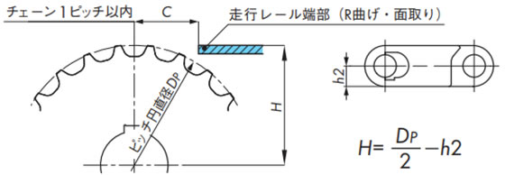
2-1-3. 走行レール端部
スプロケットと走行レール端部までの距離Cは、基本チェーン1ピッチ分設けてください。
なお、従動側走行レール端部はチェーンと走行レールの引っ掛かりを防止するためR曲げ、あるいは面取りを施してください。
2-1-4. スプロケットと走行レールの位置
下図を参照ください。
注)WT3109-W形とBTH16形については当社までお問合せください。
表6. バックベンド半径
| チェーン形式 | バックベンド半径 R mm |
|
|---|---|---|
| 幅広 | WT0405-W | 5 |
| WT0705-W | 10 | |
| BTN5, WT1505-K, WT1505RN-K, WT1505G-K, WT1505GTO-K, WT1505GTORN-K, WT1506-K, WT1515-W, WT1515G-W, WT1515VG-W, WT1516-W, WT1515G-M, BTC6, BTC6RN, BTC6-T, BTC6RN-T, BTO6, BTO6RN, BTN6 |
15 | |
| WT1907-K | 90 | |
| BTC8, BTM8H, WT2250-W, WT2525-K, WT2515-W, WT2515G-W |
25 | |
| WT2505-K, WT2506-K, WT2706-K, WTU3015T-K |
20 | |
| WT2525VG-K, WT2705-K, WT3005-K, WT3005G-K, WT3086-K, WT3086G-K |
30 | |
| WT3109-W | 35 | |
| WT3816-K, WT3835-K | 40 | |
| WT3827-K | 50 | |
| BTH16 | 60 | |
| WT5707-K | 70 | |
| 固定幅 | BTC4-M, WT0705-M | 10 |
| WT1505G-M, WT1505GTO-M, WT1505TOD-M, WT1515G-M |
15 | |
| BTO8-M, WT2505-M, WT2505G-M, WT2505TOD-M, WTM2535G-M |
20 | |
| BTC8H-M, BTM8H-M, WT2515G-M, WT2525-M |
25 | |
| WT2525VG-M, WT3005G-M, WT3086G-M, WT3085-C325 |
30 | |
| WT3835G-M | 40 | |
注)フライトタイプの場合はフライト編成・高さにより異なります。
2-2. ガイドクリアランス
熱膨張を考慮してチェーンとガイドレールとのガイドクリアランスは以下の寸法にしてください。
コンベヤのガイド幅(G) = チェーン幅(X) + ガイドクリアランス(Gc)
表7. ガイドクリアランス Gc
| チェーン幅 mm | 温度 ℃ | ||
|---|---|---|---|
| -20 ~ 40 | 40 ~ 60 | 60 ~ 80 | |
| 300以下 | 5.0 | 6.0 | 7.0 |
| 300を超え ~ 500以下 | 6.0 | 7.0 | 9.0 |
| 500を超え ~ 1000以下 | 8.0 | 11.0 | 15.0 |
| 1000を超え ~ 1500以下 | 11.0 | 15.0 | 21.0 |
| 1500を超え ~ 2000以下 | 14.0 | 20.0 | 28.0 |
| 2000を超え ~ 2500以下 | 17.0 | 24.0 | 34.0 |
| 2500を超え ~ 3000以下 | 19.0 | 27.0 | 40.0 |
注)ポリアセタール製チェーンの線膨張係数:12 × 10-5/℃
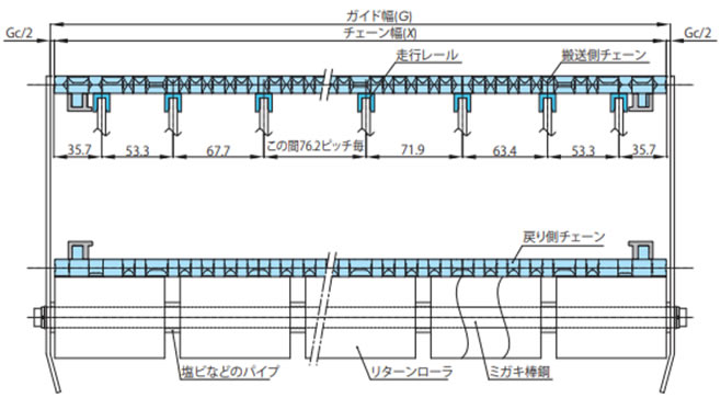
2-3. 走行レールの取付例(常温雰囲気の場合)
2-3-1. 幅広タイプ(蛇行防止アタッチメントなしの場合)
走行レールはスプロケットと交互に等間隔に配置してください。
走行レール間隔は、WT0400シリーズが45mm、WT0700シリーズ、WT1510が50mm、WT1907が50.8mm、BTN5が76mm、BT6、BT8、WT1500シリーズ、WT3005、WT3835、WT2500シリーズが76.2mm(レール幅25mm)、WT3086、WT2515、WT2250が85mm、WT3816が100mm(レール幅30mm)、WT3827、WT5707が152.4mmとなります。
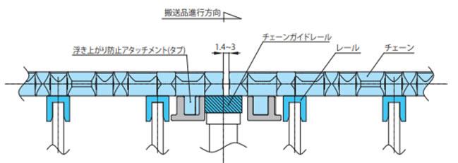
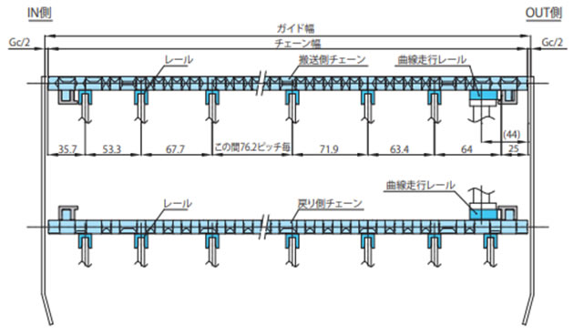
2-3-2. 幅広タイプ(蛇行防止アタッチメント(タブ)ありの場合)
(蛇行防止アタッチメント(タブ)ありチェーン:BTN5-A、WT1505G-K、WT1515G-W、WT1505GTO-K、WT1505GTORN-K、WT2515G-W、WT3005G-K、WT3086G-K、BTC8-A)
蛇行防止アタッチメント(タブ)が走行レールに干渉しないよう設置してください。
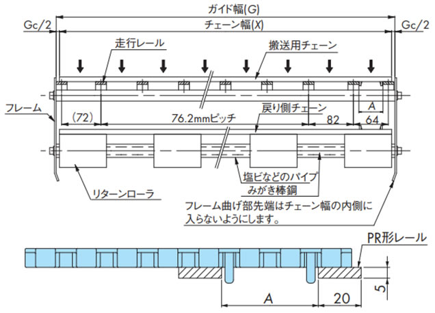
表8. A寸法一覧(幅広タイプ(蛇行防止アタッチメント(タブ)ありの場合))
| チェーン形式 | A |
|---|---|
| WT1505G-K | 44 |
| WT1505GTO-K, WT1505GTORN-K | 47 |
| BTN5-A | 44 |
| WT2515G-W | 45 |
| BTC8-A | 44 |
| WT3005G-K | 44 |
| WT3086G-K | 44 |
| WT1515G-W | 31 |
2-3-3. 幅広タイプ(WT0405-W形の場合)
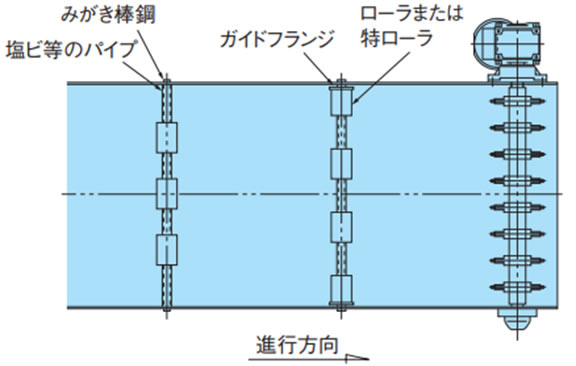
多列で使用する場合は、チェーン同士の側面が接触しないようにしてください。例を下図に示します。
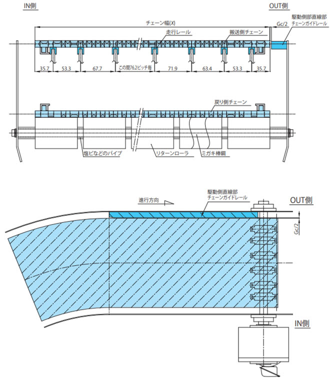
2-3-4. 幅広タイプ(WTU3015T-K形の場合)
・直線部でのレイアウト
走行レールはスプロケットと交互に等間隔に配置してください。
1) 走行レールの取付例
3) 平行渡しのレイアウト(ラップ)
直線部で平行渡しをする場合、上流側のチェーンの浮上がり防止アタッチメント(タブ)の側面に沿うようにガイドレールを設置してください。
2) 駆動側直線部のレイアウト
曲線部のあるコンベヤの駆動側直線部のOUT側にはチェーンガイドレールを設置してください。
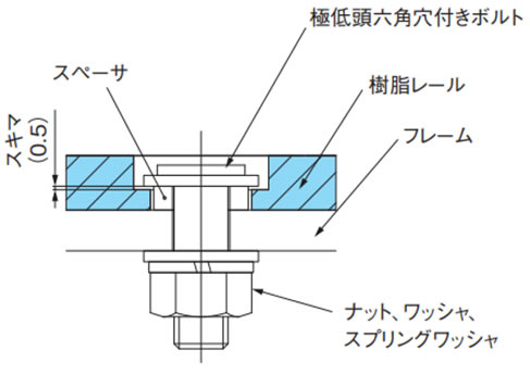
2-3-5. 幅広タイプ(WT3109-W形/BTH16形用)
一例を下記に示しますので、ご参照ください。ボルトでレールを完全にフレームに固定するのではなく、スペーサでスキマを設け熱膨張差で樹脂レールの浮きなどが発生しないよう固定してください。
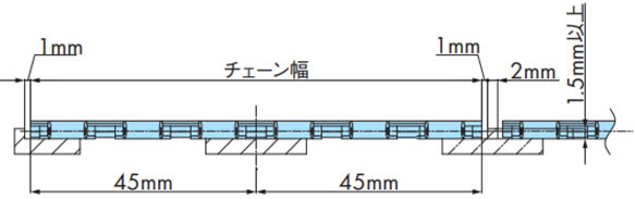
2-3-6. 固定幅タイプ(蛇行防止アタッチメント(タブ)ありの場合)
蛇行防止アタッチメント(タブ)ありチェーンのガイドクリアランスは下表を参照してください。多列で使用する際にはチェーンのスキマを1mm程度とってください。
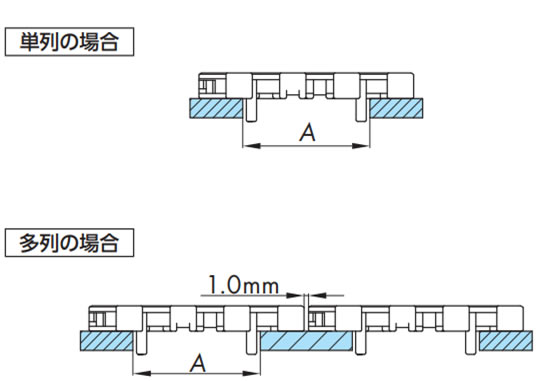
表9. A寸法一覧
(固定幅タイプ(蛇行防止アタッチメント(タブ)ありの場合))
| チェーン形式 | A |
|---|---|
| WT1505G-M | 44 |
| WT1505GTO-M | 47 |
| WT1505TOD | 53 |
| WT1515G-M50 | 31 |
| WT1515G-M100 | 61 |
| WT2505G-M | 45 |
| WT2505TOD | 45 |
| WT2515G-M | 45 |
| WTM2535G-M | 44 |
| WT3005G-M | 44 |
| WT3086G-M | 44 |
| WT3835G-M | 45 |
| BTO8-M | 44 |
| BTC8H-M | 44 |
| BTM8H-M | 44 |
2-3-7. 耐熱・高速(KV)仕様の走行レール取付
- ・走行レール材質はステンレス製を推奨します。
- ・走行レールの固定は熱膨張を考慮して一端のみ固定してください。また、走行レール間のスキマも熱膨張を考慮してください。
- ・チェーンの熱膨張を吸収するため、テークアップが必要です。テークアップ調整は必ず、使用温度に上げてから行ってください。
温度を下げる時は、必ずテークアップを緩めてから行ってください。 - ・黒い摩耗粉が発生します。定期的に清掃してください。
2-4. コンベヤのレイアウト
戻り側の受けとして、"リターンローラで受ける方式" や "走行レールで受ける方式" などがあります。下記に例を示します。
※注意事項
- 1. 特に端末でTODなどによる乗り継ぎを行う場合は注意してください。
- 2. リターン走行レールの入口部は、R40以上の大きなRを取ってください。
- 3. チェーンは温度変化により膨張・収縮しますのでカテナリ部を適切なたるみ量になるようにチェーンを切り詰め、テンショナなどで調節してください。
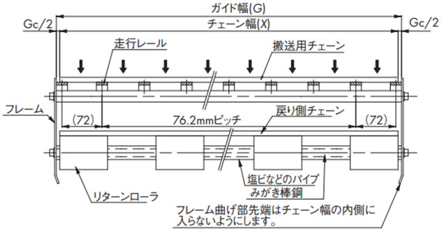
2-4-1. リターンローラで受ける方式
使用するチェーン幅に合わせてローラの取付間隔(コンベヤ幅方向)を調整します。
(コンベヤ側面)(高荷重レイアウト)
注)
- WT1907、WT3827、WT5707はΦ80以上。
L寸法は上記表5を参照ください。
(コンベヤ戻り側平面)
2-4-2. 走行レールで受ける方式
(コンベヤ側面)(高荷重レイアウト)
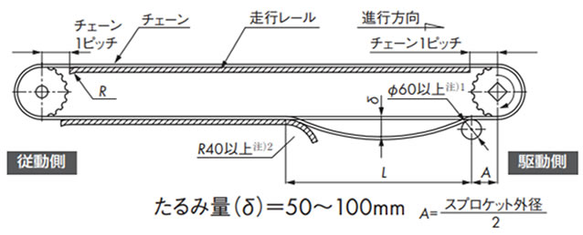
注)
- 1. WT1907、WT3827、WT5707はΦ80以上。
- 2. WT1907、WT3827、WT5707はバックベンド半径以上。
L寸法は上記表5を参照ください。
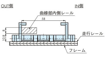
2-4-3. 曲線部でのレイアウト(WTU3015T-K形の場合)
曲線搬送の場合、戻り側カテナリ確保のために駆動部~カーブ部分まで直線部分を800mm以上設けるようにしてください。
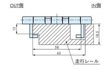
1) 走行レールの取付例
2) 走行レール入口・出口部の処理
曲線走行レールの入口・出口の直線走行レールへ乗り移る部分はチェーンの引掛りを防止するため「面取り」を施してください。
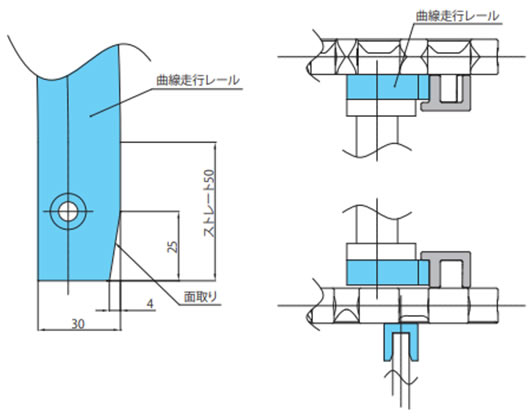
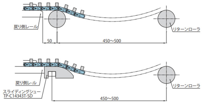
・戻り側曲線部でのレイアウト
戻り側カーブドレールの両端部には、チェーンの案内用として、レールから50mm離れた所にリターンローラまたはスライディングシュー(TP-C14343T-SD)を設置してください。
コンベヤ側面断面図
2-4-4. 曲線部でのレイアウト(WT3085-C形の場合)
搬送側曲線部での走行レールの取付
戻り側曲線部での走行レール取付
(アタッチメント摺動)
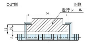
(トッププレート摺動)
2-5. WT0700シリーズ両端ノーズバーの取付例
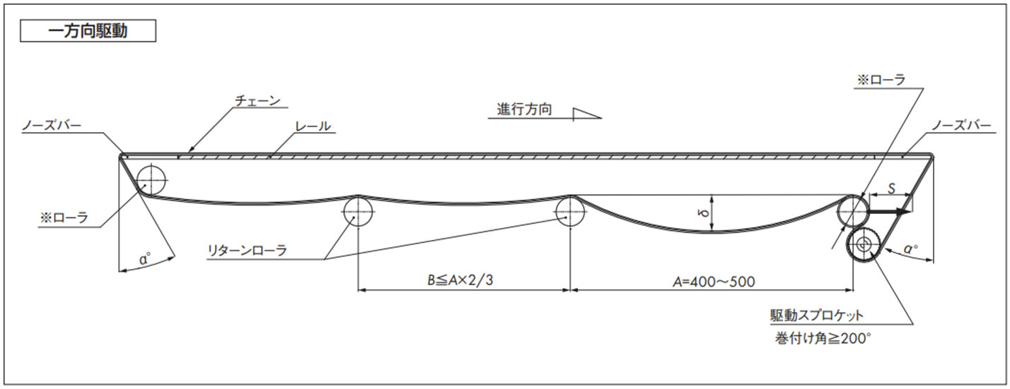
コンベヤ設計上の注意点
- 1. ※ローラはテークアップ式にしてください。
- ・チェーン伸びの吸収、切り継ぎ、たるみ(δ)調整などが容易になります。
- ・テークアップストローク(S)の目安は S = 機長 × 1%
- 2. ※ローラ部について
- ・外径はΦ50以上のできる限り大きい物を選定してください。
- ・使用する軸は十分な剛性が必要です。
- ・必ず回転させてください。
- 3. チェーンは温度変化により膨張・収縮しますので、カテナリ部が適切なたるみになるようチェーンを切継ぐか、テンショナなどで調節してください。
[参考:ポリアセタール製チェーンの線膨張係数:12 × 10-5/℃]
- 4. 正逆底部駆動での※ローラ部には使用張力の約1.5倍の負荷が作用しますので、機幅の広いコンベヤ(1m以上)の場合は、十分な剛性を持った軸を選定するか、3点支持以上で軸を受けるようにしてください。
ノーズバーを使用する際の注意点
- 1. ノーズバーを取り付けるブレーシングは剛性を持たせ、たるみを0.5mm以内に抑えてください。
- 2. コンベヤ幅方向に対するフレームの曲がり、ねじれなどの許容誤差寸法は、0.3mm以内にしてください。
- 3. ノーズバーと※ローラおよびスプロケットの位置寸法は、角度α≦30°になるように設定してください。
- 4. ノーズバーは最大使用張力に近い負荷でチェーンと摺動しますので、ドライ条件、高速走行および重荷重搬送の場合は、SJ-CNO(特殊ポリアミド)製を推奨します。
注)本設計資料は重荷重条件を加味した仕様です。
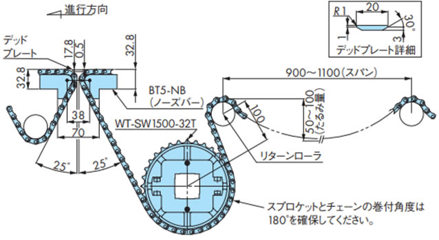
2-6. WT1500シリーズおよびBTN5と両端ノーズバーの取付例
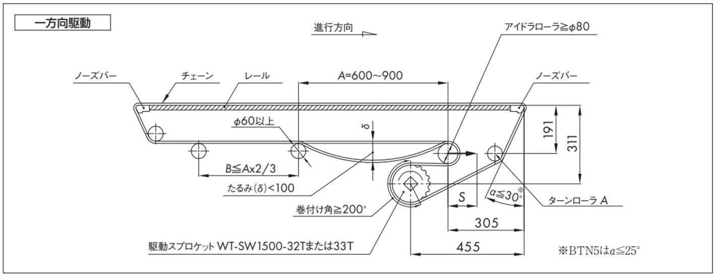
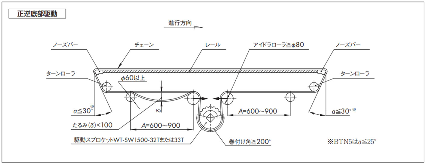
コンベヤ設計上の注意点
- 1. アイドラローラはテークアップ式にしてください。
- ・チェーン伸びの吸収、切り継ぎ、たるみ(δ)調整などが容易になります。
- ・テークアップストローク(S)の目安は S = 機長 × 1%
- 2. アイドラローラの外径は、Φ80以上のできる限り大きい物を選定してください。
- 3. アイドラローラは必ず回転させてください。
- 4. ターンローラA、ターンローラに使用する軸は十分な剛性が必要です。(ターンローラに高回転性リターンローラは使用しないでください)
- 5. チェーンは温度変化により膨張・収縮しますので、カテナリ部が適切なたるみになるようチェーンを切継ぐか、テンショナなどで調節してください。
[参考:ポリアセタール製チェーンの線膨張係数:12 × 10-5/℃]
- 6. 正逆底部駆動でのアイドラローラ部には使用張力の約1.5倍の負荷が作用しますので、機幅の広いコンベヤ(1m以上)の場合は、十分な剛性を持った軸を選定するか、3点支持以上で軸を受けるようにしてください。
ノーズバーを使用する際の注意点
- 1. ノーズバーを取り付けるブレーシングは剛性を持たせ、たるみを0.5mm以内に抑えてください。
- 2. コンベヤ幅方向に対するフレームの曲がり、ねじれなどの許容誤差寸法は、0.3mm以内にしてください。
- 3. ノーズバーとターンローラの位置寸法は、角度α≦30°になるように設定してください。
- 4. ノーズバーは最大使用張力に近い負荷でチェーンと摺動しますので、ドライ条件、高速走行および重荷重搬送の場合は、材質グレードPLFやSJ-CNO(特殊ポリアミド)を推奨します。
注)本設計資料は重荷重条件を加味した仕様です。
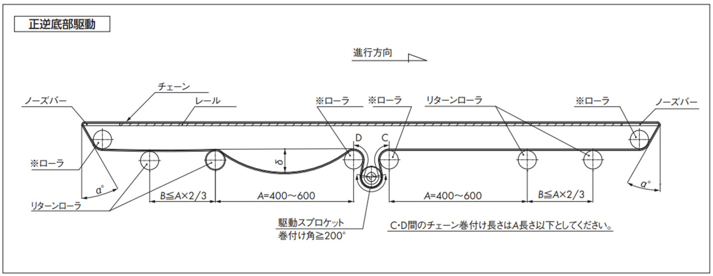
2-7. WT2520シリーズの正逆底部駆動のレイアウト
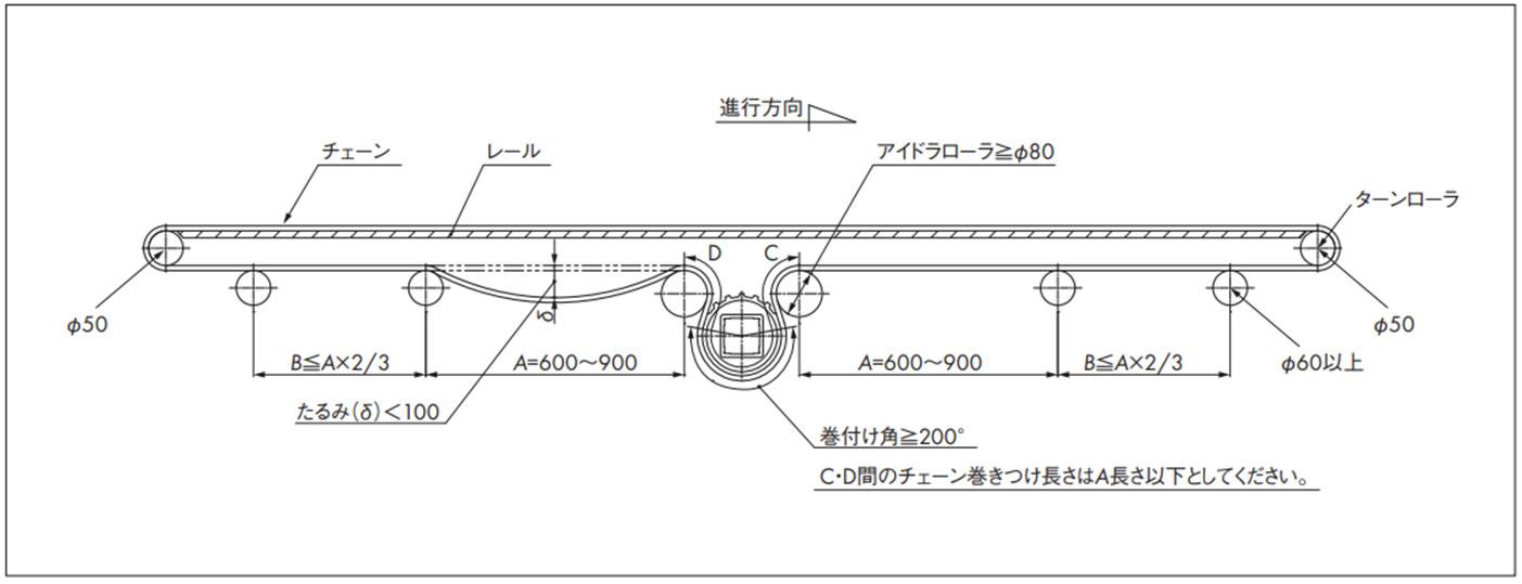
コンベヤ設計上の注意点
- 1. アイドラローラの外径は、Φ80以上のできる限り大きい物を選定してください。
- 2. アイドラローラは必ず回転させてください。
- 3. ターンローラに使用する軸は十分な剛性が必要です。(ターンローラに高回転性リターンローラは使用しないでください)
- 4. チェーンは温度変化により膨張・収縮しますので、カテナリ部が適切なたるみになるようチェーンを切継ぐか、テンショナなどで調節してください。
[参考:ポリアセタール製チェーンの線膨張係数:12 × 10-5/℃]
- 5. 正逆底部駆動でのアイドラローラ部には使用張力の約1.5倍の負荷が作用しますので、機幅の広いコンベヤ(1m以上)の場合は、十分な剛性を持った軸を選定するか、3点支持以上で軸を受けるようにしてください。
2-8. ノーズバーの突合せレイアウト
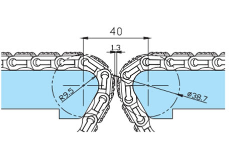
2-8-1. WT0405-W形の突合せレイアウト
R2.5mmノーズバーを使用することによりコンベヤ同士の突合せレイアウトが可能です。
従来必要としたデッドプレートを使用せず13mmまで狭くすることが可能です。
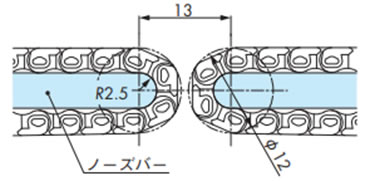
注)詳細は当社までお問合せください。
2-8-2. WT0700シリーズの突合せレイアウト
・WT0700シリーズノーズバー突合せレイアウト
コンベヤ間での接続をストレートに突合せすることが可能です。
デッドプレートを使用し最小距離まで狭くすることが可能です。
・WT0700シリーズノーズバーとスプロケット突合せレイアウト
コンベヤ間での接続をスプロケットとストレートに突合せすることが可能です。
デッドプレートを使用し最小距離まで狭くすることが可能です。
・WT0700シリーズノーズバーとWT1500シリーズスプロケット突合せレイアウト
コンベヤ間での接続をスプロケットとストレートに突合せすることが可能です。
デッドプレートを使用し最小距離まで狭くすることが可能です。
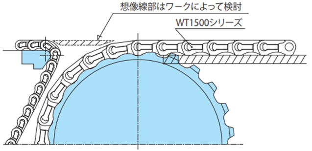
2-8-3. WT1500シリーズ、BTN5形の突合せレイアウト
デッドプレートの配置は設置スペースなどにより異なりますが一例を下図に示します。
注)
- 1. 上図中寸法は参考値です。搬送物の乗移り状態により微調整してください。
- 2. 搬送物の形態(不安定)によっては、わずかなチェーンのシャクリにより不具合を生じる可能性があります。そのような搬送物の場合は、お問合せください。
WT1500、WT1510シリーズやBTN5形を使用することにより、コンベヤ間での接続をストレートに突合せすることが可能です。
突合せ部に使用するデッドプレートは20mmまで狭くする事が出来ます。
注)
- 1. ※部は搬送物の違いにより調整が必要です。
- 2. 対応チェーンはWT1500、WT1510シリーズとBTN5形のみです。なおWT1505Gは適応できません。
・WT1500、WT1510シリーズノーズバー突合せレイアウト
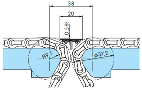
・WT1515VG-W形突合せレイアウト
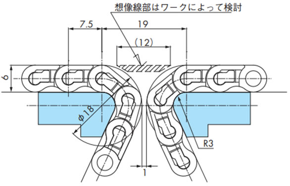
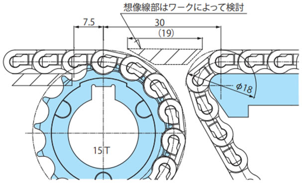
2-9. BTC4-M形の突合せレイアウト
・歯数10Tスプロケットで直線乗移りの場合
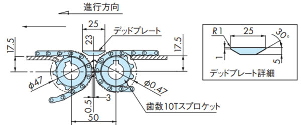
・Φ18シャフトで直線乗移りの場合
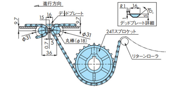
注)デッドプレートのレベルは搬送物の乗移り状態により微調整ください。
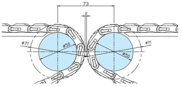
2-10. WT2520シリーズの突合せレイアウト
コンベヤ端部にΦ50の丸棒を設置することでコンベヤ間の乗継ぎスペースを小さくすることが可能です。正逆底部駆動でのレイアウトとなります。
・WT2525-K形/WT2525-M形突合せレイアウト
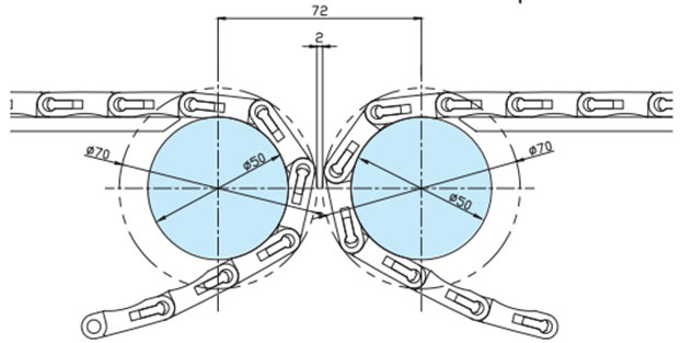
・WT2525VG-K形/WT2525VG-M形突合せレイアウト
2-11. 直交搬送レイアウト
当社ノーズバーやGTO/TODタイプチェーンを使用することで、通常必要とされるデッドプレートを使用することなく搬送物のスムーズな90°変換移送を可能にしています。
・各チェーンの取付け寸法を以下に示します。
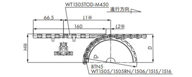
挿入搬送(WT1505TOD/WT1500)
| 歯数 | 寸法 mm | ||||
|---|---|---|---|---|---|
| Dp | D | H※ | L1※ | L2※ | |
| 24 | 114.9 | 61.4 | 62.2 | 103.9 | 10.4 |
| 32 | 153.0 | 80.5 | 81.3 | 104.9 | 11.4 |
| 33 | 157.8 | 82.9 | 83.7 | 105.0 | 11.5 |
注)※部は搬送物の違いにより調整が必要です。
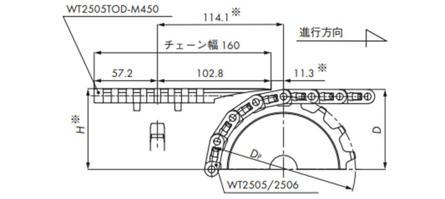
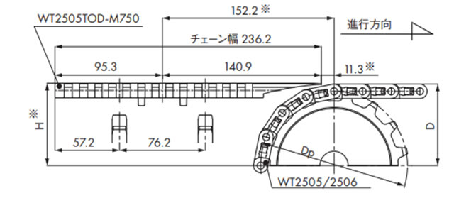
挿入搬送(WT2505TOD/WT2500)
・WT2505TOD-M450の場合
| 歯数 | 寸法 mm | ||
|---|---|---|---|
| Dp | D | H※ | |
| 16 | 130.2 | 71.4 | 72.1 |
| 18 | 146.3 | 79.5 | 80.3 |
| 21 | 170.4 | 91.6 | 92.5 |
| 31 | 251.1 | 131.8 | 132.6 |
注)※部は搬送物の違いにより調整が必要です。
・WT2505TOD-M750の場合
| 歯数 | 寸法 mm | ||
|---|---|---|---|
| Dp | D | H※ | |
| 16 | 130.2 | 71.4 | 72.1 |
| 18 | 146.3 | 79.5 | 80.3 |
| 21 | 170.4 | 91.6 | 92.5 |
| 31 | 251.1 | 131.8 | 132.6 |
注)※部は搬送物の違いにより調整が必要です。
排出搬送(WT1505GTO/WT1505GTORN/WT1500)
注)※部は搬送物の違いにより調整が必要です。
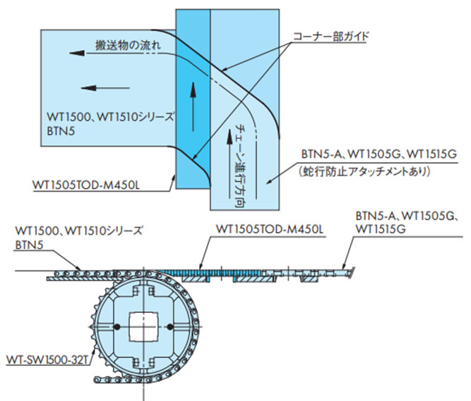
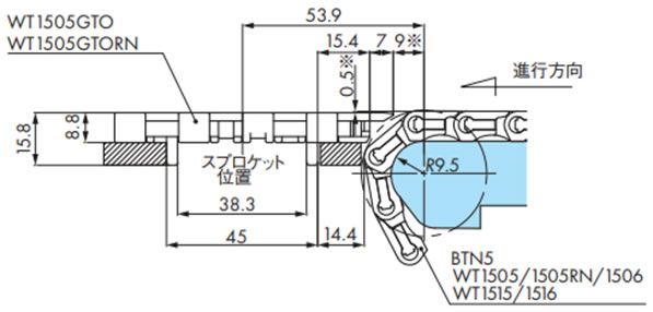
2-12. WT1500とWT1505Gの直交搬送
挿入搬送(WT1500/WT1505G/WT1515G)
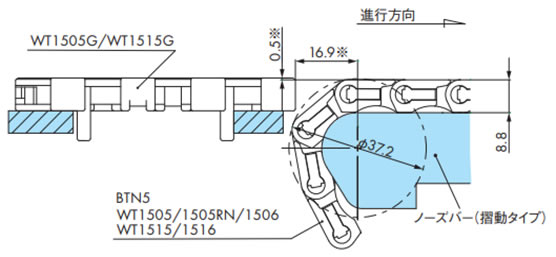
注)※部は搬送物の違いにより調整が必要です。
排出搬送(WT1500/WT1505G/WT1515G)
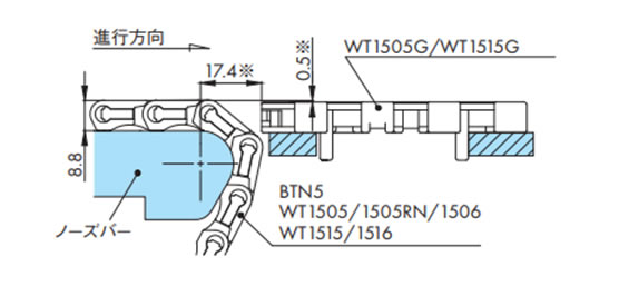
注)※部は搬送物の違いにより調整が必要です。
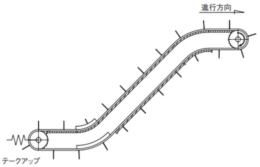
2-13. 傾斜コンベヤのテークアップ
傾斜コンベヤでは、チェーンの自重により従動スプロケットからチェーンが外れる可能性があります。そのため、テークアップを設置することをお勧めします。
傾斜搬送(水平+傾斜+水平)のテークアップ
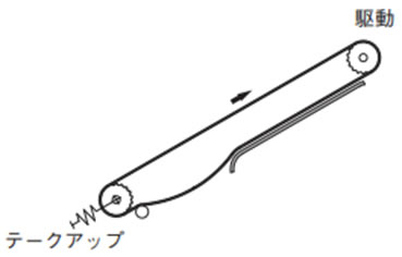
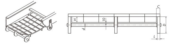
2-14. フライトタイプチェーンの戻り側
ローラ受け参考例
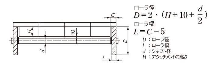
チェーンのたわみ受けの為に、チェーン幅によってリターンローラ支持数を増やす必要があります。
注)フライト部分の干渉を避けるためにフライトの追加工が必要です。
参考図
2-15. 浮上がり防止アタッチメント(タブ)の特殊編成
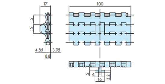
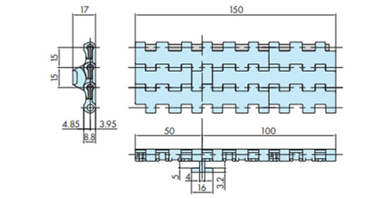
WT1515T-F-W形において、チェーン幅が100㎜と150㎜の際は浮上がり防止アタッチメント(タブ)の編成が異なります。
チェーン幅100mm
チェーン幅150mm
2-16. トランスファプレートの設置
トランスファプレートの望ましい配置を下記に示します。
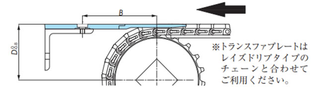
| チェーン形式 | トランスファプレート形番 | B mm | D mm |
|---|---|---|---|
| WT1907-K | WT-TP1907-L114 | 70 | Dp2 + 9.9 |
| WT-TP1907-L190 | 100 | ||
| WT3827-K | WT-TP3827-L152 | 82 | Dp2 + 12.7 |
| WT5707-K | WT-TP5707-L220 | 82 | Dp2 + 15.5 |
Dp:ピッチ円直径
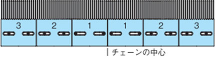
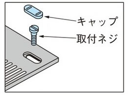
トランスファプレートに付属するキャップと取付ネジは右図のとおり取付けてください。
またトランスファプレートはチェーンの熱膨張を考慮し、使用温度条件により下図の通り取付ネジを設置してください。
- 1) 室温(20℃)で温度変化のない場合
2、3のトランスファプレートの取付ネジは長穴の中央に設置してください。
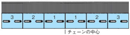
- 2) 低温の場合
2、3のトランスファプレートの取付ネジはチェーンの中心よりに設置ください。
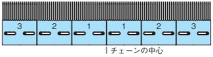
- 3) 高温の場合
2、3のトランスファプレートの取付ネジはチェーンの端よりに設置ください。