技術資料 トップチェーン 選定
このページはトップチェーン・プラブロックチェーンの製品の共通ページです。
このページでは以下の項目について紹介しています。
(各項目をクリックすると本文にスクロールできます。)
- 2-1. 駆動・従動側の走行レール取付け
- 2-2. 搬送側直線部での走行レール(プラレール)取付け
- 2-3. 搬送側曲線部での走行レールの取付
- 2-4. 戻り側直線部でのレイアウト
- 2-5. 戻り側曲線部でのレイアウト
- 2-6. TPUSR形チェーンのコーナディスクを用いた曲線部
- 2-7. TPUN-LH形のコンベヤ設計
- 2-8. TPUH-BO形の水平コンベヤ設計
- 2-9. プラクレセント®のコンベヤチェーン
- 2-10. コンベヤの継足し
- 2-11. 耐熱・高速(KV)仕様トップチェーン使用上の留意点
コンベヤ設計資料
レールの配置は設置スペースなどにより異なりますが一例を下図に示しています。なお、戻り側のレイアウトは、下記2-4項を参照ください。
注)プラスチックモジュラーチェーン(固定幅)のコンベヤ設計資料も参照ください。
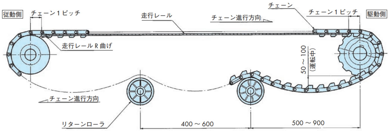
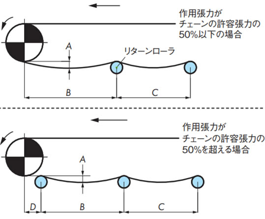
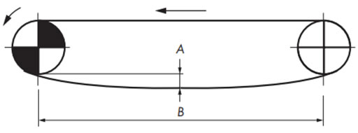
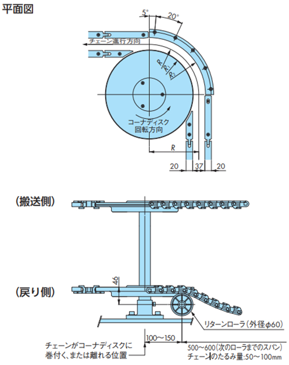
- 1)チェーンのたるみ量
戻り側チェーンを受けるリターンローラの間隔は500~900mm間隔としてリターンローラ間のチェーンのたるみ量は50~100mmとしてください。このたるみにより歯飛びを防止しています。この間隔、たるみ量の範囲以外では歯飛びする場合があります。 - 2)かみ合い角度
駆動スプロケットとチェーンの「かみ合い角度」は150°以上にしてください。 - 3)走行レール端部
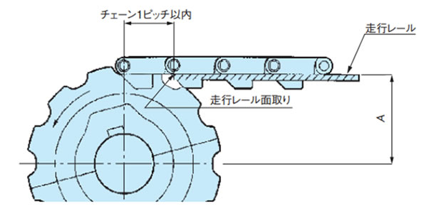
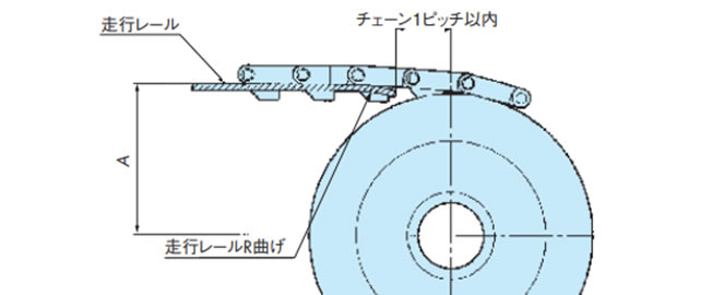
駆動、および従動側の走行レール端部から、各々のシャフトセンターまでは、チェーン1ピッチ以内の距離を設けてください。なお、従動側走行レール端部はチェーンと走行レールの引っ掛かりを防止するためR曲げ、あるいは面取りを施してください。
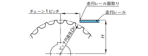
2-1. 駆動・従動側の走行レール取付け
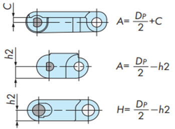
2-1-1. スプロケットと走行レールの位置
[駆動側]
プラスチックモジュラーチェーン(固定幅)の場合
[従動側]
トッププレート付チェーン用
アイドラホイール(歯形なし)の場合
プラトップチェーン・
ステンレストップチェーン
プラブロックチェーン・
プラユニバーサルチェーン
プラスチック
モジュラーチェーン(固定幅)
注)
- 1. DP:ピッチ円直径
- 2. アイドラホイールは相当歯数のスプロケットのピッチ円直径を適用してください。
2-2. 搬送側直線部での走行レール(プラレール)取付け
2-2-1. 搬送側の受け
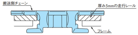
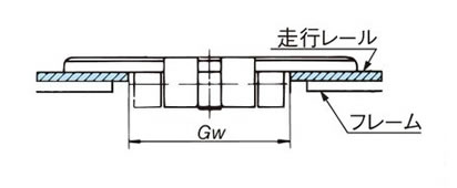
- 1. ガイド幅Gwはチェーン本体のヒンジ幅より2mm程度広くします。(図1)(ガイド幅Gwは2-2-4.を参照ください。)
- 2. 多列ラインでチェーン進行方向が逆方向または同一でも速度の異なる場合はT形レールなどを使用しチェーンのトッププレートが接触しないようにします。(図2)
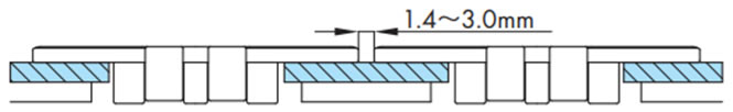
- 3. 多列ラインで進行方向、速度が同一の場合はチェーンのトッププレートの間隔は1.4~3mmを推奨します。(図3)
- 4. フレーム自体の摩耗が生じないように、走行レールのご使用を推奨します。
- 5. 走行レールの厚みは摩耗を考えて3mm以上必要です。
図1. チェーンの搬送側の受け
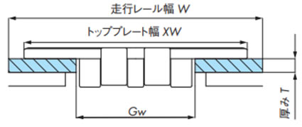
図2. 多列で進行方向が逆、または速度差がある場合
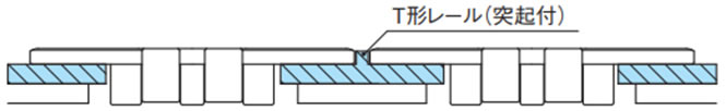
図3. 多列で速度同一の場合
2-2-2. 浮上り防止アタッチメントありチェーン使用時の走行レール
2-2-3. 直線走行レールの取付け
・PR形レール、PH形レール、フラットレール
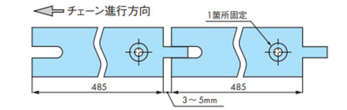
熱による膨張を考慮してフレームへの固定は端部一ヵ所ネジ止めとして、接合部はスキマをあけてください。
(PH形レールのスキマ:3~5mm)
注)
- 1. 線膨張係数
プラレール(Pレール)、PLFレール:20×10-5/℃
Mレール:9×10⁻⁵/℃ - 2. プラレールの使用温度範囲
プラレール(Pレール)、PLFレール:-20~60℃
Mレール:-20~80℃ - 3. 蒸気の掛かる条件では走行レールを使用しないでください。
- 4. 耐熱・高速(KV)仕様の走行レールについては下記2-11項を参照ください。
・長尺直線タイプ(Z形、T形、L形、フラット形などの押出走行レール)
[コンベヤ機長が長い場合]
仮に長尺直線タイプの走行レールを1m単位で設置する場合、走行レール間のスキマはチェーンの落込み防止のため、下図のように加工してください。
(長尺直線タイプのスキマ:1mあたり10mm程度)
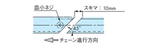
注)1m以上の場合、線膨張係数からスキマ寸法を算出してください。
[コンベヤ機長が短い場合]
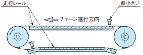
走行レールの両端を皿小ネジで数ヵ所固定すると、フレーム(金属製)との線膨張係数の差により、走行レールが波打ちの状態になるため、皿小ネジは端部一ヵ所で止めてください。
2-2-4. チェーンと走行レール内間隔とのクリアランス(直線部)
[プラトップチェーン・ステンレストップチェーン]
[プラブロックチェーン]
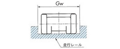
表9.プラトップチェーン・ステンレストップチェーン
| 形式 | ガイド幅 Gw mm |
|---|---|
| TTP, TTPH, TPF, TPS, TP-OTD, TPH, TPM, TPM-SN, TT | 44 |
| TTPDH, TTPDH-LBP | 140 |
| TN | 38 |
| TPRF2040, TP-1843G | 23 |
| TPRF2060, TS, TTUPM-P, TTUPM-PC | 32.5 |
| TTPT, TSA | 44.5 |
| TTUP, TTUPH, TTU, TTUPS-H | 43 |
| TPU, TPUM | 44 |
| TPU-USR | 46 |
| TPUS | 58 |
| TPUS-LBP, TPUS-Y-LAP | 60 |
| TPUSR, TP-PTS | 37 |
| TNU | 38 |
| TRU, TTUP-LLPC | 44.5 |
| TTUP(T)-M, TPU(T)-LH, TPUH-BO, TTKU, TO, TU, TTUPM838H | 45 |
| TTPM | 32 |
| TPSS | 62 |
| TTUPS | 61.5 |
| TP-36AK | 31 |
| TP-PT, TP-1873T, TP-UB36 | 34 |
| TP-1873G | 35 |
| TP-30UTW-LAP | 50.5 |
| TP-36UTW-LAP | 62 |
| TOSP | 27 |
| TORP | 48 |
表10. プラブロックチェーン・プラユニバーサルチェーン
| 形式 | ガイド幅 Gw mm |
|---|---|
| TPUN, TPUN-LH, TP-50UNS, TP-50UNS-D76 注)1 | 58 |
| TP-50UN-T95 | 53 |
| RSP35 | 16 |
| RSP40, RSP40-SL300 | 23 |
| RSP50 | 25.5 |
| RSP40-T-CU | 34 |
| RSP60, RSP60-CU | 33 |
| RSP60-2 | 63 |
| RSP60-CU-2 | 66 |
| RSP80 | 43 |
| RSP50-SL350 注)2 | 26 |
注)
- 1. TPUN形、TPUN-LH形のレール高さは15~22mm程度を推奨します。
- 2. トッププレート面で受ける場合ガイド幅Gwは24になります。
- 3. 同じ形式のプラピンタイプはステンレスピンタイプと同じガイド幅Gwになります。
2-3. 搬送側曲線部での走行レールの取付
2-3-1. 曲線走行レールの設置処理
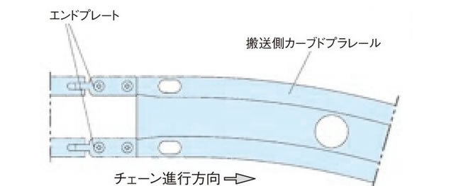
・入口部の処理
カーブドプラレールの入口手前の直線走行レールにはエンドプレートを取付けます。
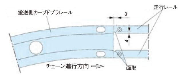
・出口部の処理
カーブドプラレールの出口直後の直線走行レールにはチェーンの引っ掛りを防止するため「面取り」を施してください。(走行レールを加工してください。)
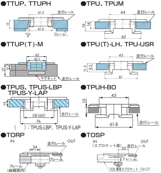
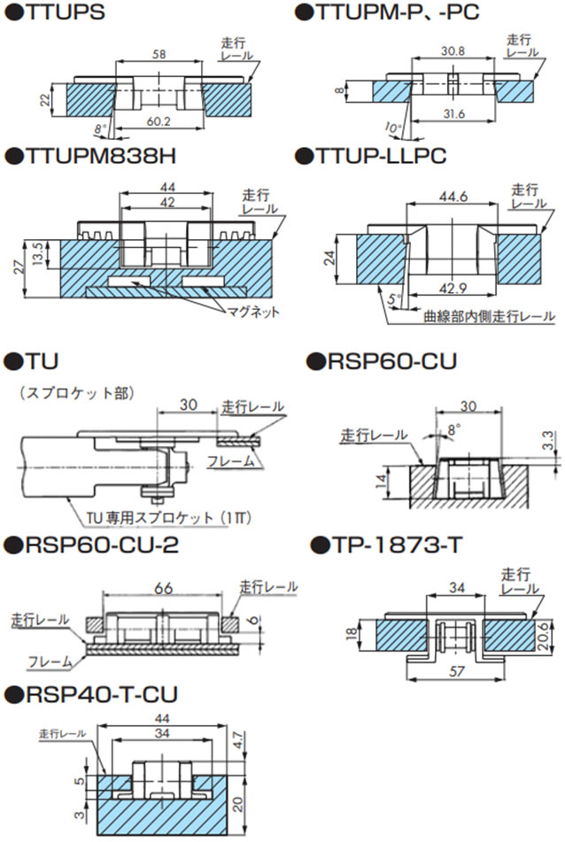
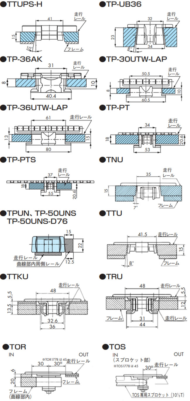
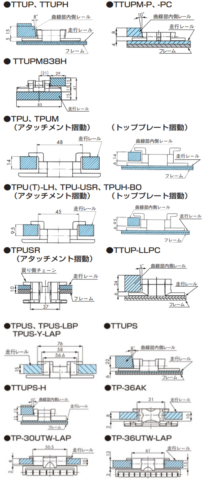
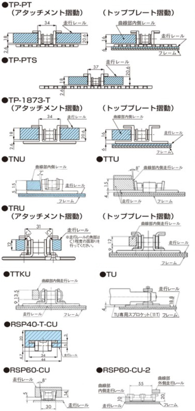
2-3-2. 各チェーンと走行レール断面
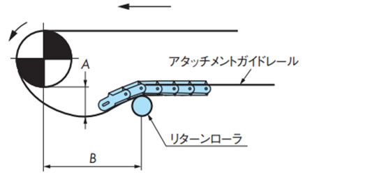
2-4. 戻り側直線部でのレイアウト
戻り側のレイアウトは、チェーンの種類・搬送物の種類・形式・経路などによって異なりますが、一般的なレイアウトを以下に示します。
|
リターンローラで受ける方式最も一般的で、推奨するレイアウトです。
|
|
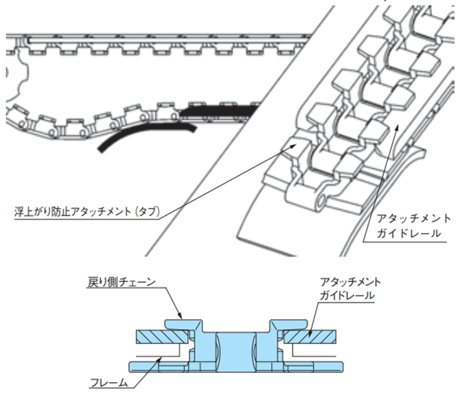
浮上がり防止アタッチメント(タブ)摺動による方式浮上がり防止アタッチメント(タブ)を受けることでトッププレート上面の摺動をなくせます。 特にトッププレート上面にキズをつけたくない搬送条件に適してます。
|
|
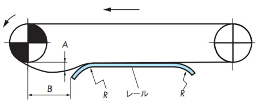
走行レールで受ける方式トッププレートの局部だけを受けると偏摩耗する可能性があります。 走行レールはトッププレート全面に当たるように、八の字形あるいは波状などに設置し、異物などが簡単に落ちる構造にしてください。
|
|
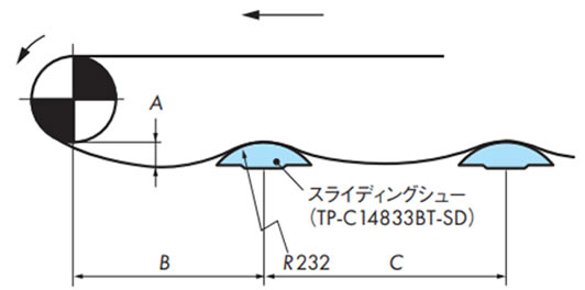
スライディングシューで受ける方式比較的低速(50m/min以下)の搬送条件に適します。 一般的にはアキュムレーションチェーン(TTPDH-LBP)やプラローラテーブル(ST、RT)に適します。
|
|
レールのみを使用する方式合理的なレイアウトですが、摺動によりトッププレート上面にキズがつくというデメリットもあります。 バックベンド半径が比較的大きいチェーンに適します。
|
|
戻り側は支持しない方式戻り側のチェーンの概略質量による張力が振動の原因になり、搬送が不円滑になる場合があります。 コンベヤの機長が短い場合(1.5m以下)でやむなくこの方式にする場合は、従動側でテークアップ機構を設けるか、チェーンが伸びた場合に切継ぎを行い、チェーンのスプロケットへのかみ合い角度=150°以上を確保してください。
|
2-4-1. 戻り側レイアウト詳細
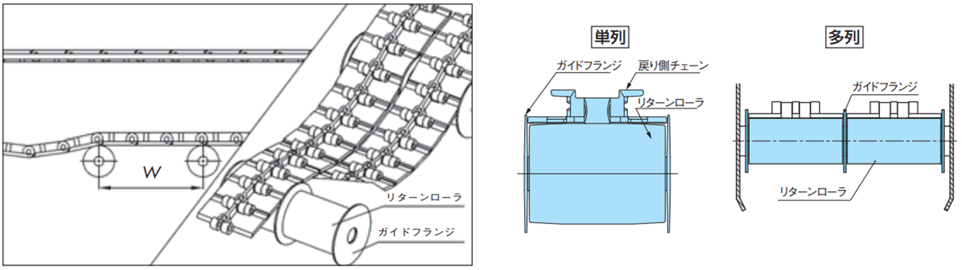
・リターンローラで受ける方式
- ・リターンローラは戻り側でチェーン上面を受けるアイテムです。
- ・リターンローラは、表11のチェーンバックベンド半径を考慮してお使いください。基本的にチェーンのバックベンド半径≦リターンローラの半径を推奨しますが、バックベンド半径がR300程度までであれば、チェーンのたるみ量を小さく維持することで使用は可能です。ただし、プラローラテーブルやアキュムレーションチェーンには不適です。
- ・特にプラトップチェーンを使用する場合に、リターンローラの回転性をあげるために、リターンローラの内外径比は[内径:外径=1:4以上]を推奨します。さらにリターンローラ外周に軟質材を使用したTP-IR18、TP-IR60(ドライ条件専用)、TP-C121963RNT-RR、TP-C121966RNT-RR、TP-C121967RNFT-RR、TP-C121970RNFT-RR、TP-RR61544-RB、TP-RR62032-RB、TP-RR62044-RB、TP-RR30850、TP-RR41050(ドライ&ウェット条件兼用)では回転性向上に効果があります。
注)高回転性リターンローラはチェーン速度50m/min以下でご使用ください。
・浮上がり防止アタッチメント(タブ)摺動による方式(特にスラット上面にキズをつけたくない場合)
・走行レールで受ける方式
チェーン搬送面の摩耗を考慮し、チェーン幅に対して均等に接触するように走行レールを配置してください。ベタ受けは避け、異物などが簡単に落ちる構造にしてください。
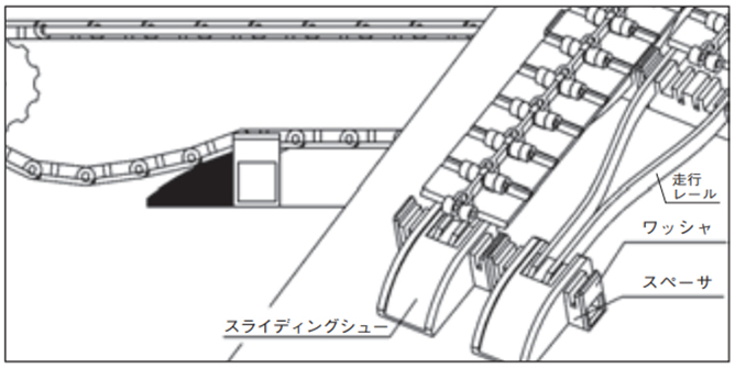
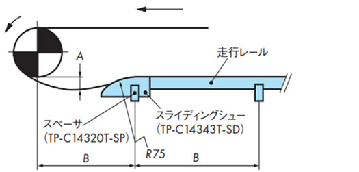
・スライディングシューで受ける方式
Φ20ミガキ棒鋼をフレームに固定し、その棒鋼にスライディングシューをスナップして取付けてください。このときスライディングシューが左右に振れないようにセットカラーなどを用いてください。
スライディングシューは棒鋼を支点としてチェーンの動きに合わせて揺れます。
★印は多列コンベヤにおいて横に並ぶスライディングシュー同士を連結するための穴です。
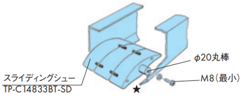
表11. チェーンバックベンド半径
| タイプ | チェーン | バックベンド 半径 mm |
|---|---|---|
| プラトップ/直線 | TTP | 40 |
| TTPT, TTPDH | 50 | |
| TTPM | 25 | |
| TPF, TPS | 40 | |
| TP-OTD | 50 | |
| TPH, TTPH | 35 | |
| TPSS | 50 | |
| TPM(-SN) | 15 | |
| TPRF2040 | 380 | |
| TPRF2060 | 50 | |
| TN | 100 | |
| TTPDH-LBP | 400 | |
| プラブロック/直線・曲線 | RSP35 | 80 |
| RSP35-KV180 | 150 | |
| RSP40 | 125 | |
| RSP40-SL300 | 50 | |
| RSP40-T-CU | 25 | |
| RSP50 | 155 | |
| RSP50-SL350 | 140 | |
| RSP60, RSP80 | 180 | |
| RSP-PO8PF | 125 | |
| RSP-PO8PFT | 125 | |
| RSP60-2 | 450 | |
| RSP60-CU | 250 | |
| RSP60-CU-2 | 150 | |
| ステンレストップ/直線 | TT | 180 |
| TS, TSA, TS-CTP, TSA-HTP | 330 |
| タイプ | チェーン | バックベンド 半径 mm |
|---|---|---|
| プラトップ/曲線 | TTUP, TPU, TPU-USR, TTUPS | 40 |
| TTUPS-H | 170 | |
| TTUPH | 35 | |
| TTUP(T)-M, TPU(T)-LH, TPUH-BO, TPUS | 50 | |
| TTUPM-P | 20 | |
| TTUP-LLPC | 70 | |
| TTUPM838H | 100 | |
| TP-UB36, TTUPM-PC | 30 | |
| TPUM | 15 | |
| TPUSR826 | 25 | |
| TPUSR550 | 50 | |
| TP-36AK | 75 | |
| TNU | 100 | |
| TP-PT, PTS | 150 | |
| TP-1873T | 305 | |
| TP-1843G, 1873G | - | |
| TPUS-LBP | 400 | |
| TPUS-Y-LAP | 250 | |
| TP-30UTW-LAP | 180 | |
| TP-36UTW-LAP | 160 | |
| TPUN555, TPUN-LH | 25 | |
| TP-50UNS | 25 | |
| TP-50UNS-D76 | - | |
| TP-50UN-T95 | 500 | |
| TPCC | 35 | |
| TORP, TOSP | - | |
| ステンレストップ/曲線 | TTU | 100 |
| TTKU, TRU | 300 | |
| TO, TU | - |
注)
- 1. "-"は(ほとんど)バックベンドしないチェーンを示しています。
- 2. RSP60のモデルチェンジ前のバックベント半径は450mmです。
- 3. 同じ形式のプラピンタイプはステンレスピンタイプと同じバックベンド半径です。
2-5. 戻り側直線部でのレイアウト
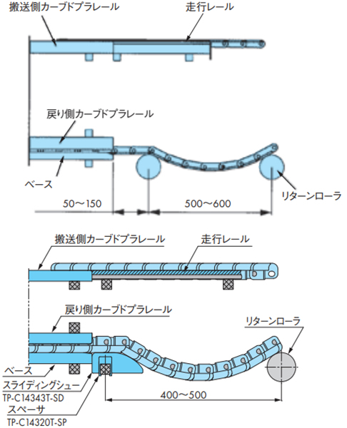
2-5-1. 戻り側カーブドプラレールの設置
戻り側カーブドプラレールの両端部には、チェーンの案内用として、ベースから50~150mm離れた所にリターンローラまたはスライディングシュー(TP-C14343T-SD)を設置してください。
コンベヤ側面断面図
2-5-2. 各チェーンと走行レール断面
注)TPUSR、TPUN550-LH、TPUN535-LH、TP-UB36、TP-50UNS、TP-50UNS-D76はコーナディスクをご使用ください。
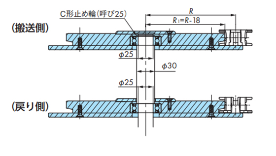
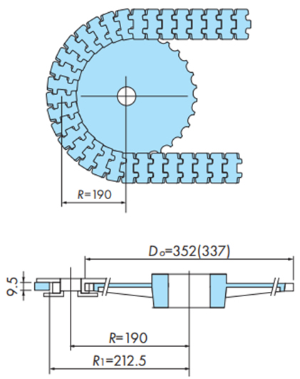
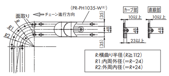
2-6. TPUSR形チェーンのコーナディスクを用いた曲線部
・TPUSR826
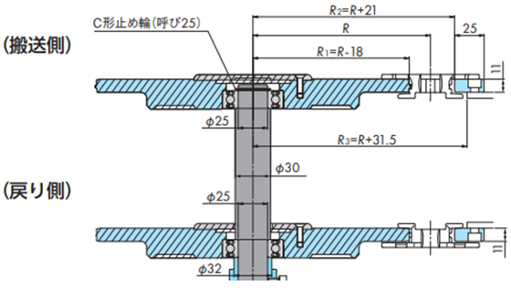
・TTPUSR550
(記号の説明)
- ・R:チェーンの横曲り半径(mm)
- ・R1:コーナディスク外周半径(mm)
- ・R2:チェーン外側走行レールの内周半径(mm)
- ・R3:外側走行レール固定用コンベヤフレームの内周寸法(mm)
戻り側直線部を、リターンローラで受けるコンベヤの場合は、下図のようにコーナ部の入口と出口に案内のためリターンローラを必ず設置してください。
注)ドライ条件でのご使用を推奨します。
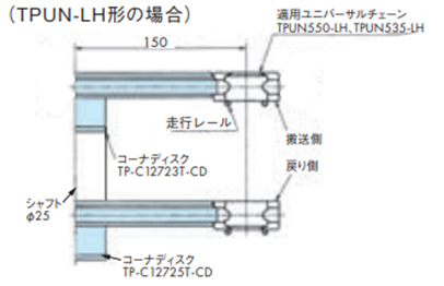
2-7. TPUN-LH形のコンベヤ設計
2-7-1. 走行レールを使用する場合
・棒状レール
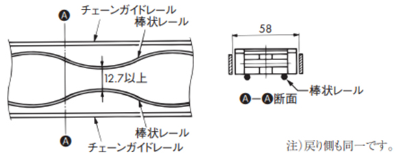
・板状レール
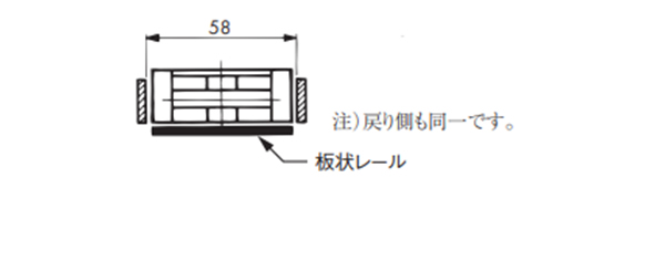
2-7-2. コーナディスクを使用する場合
・曲線部
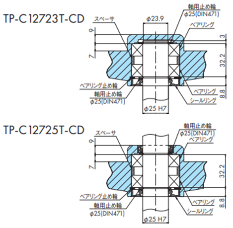
・コーナディスクの取付け
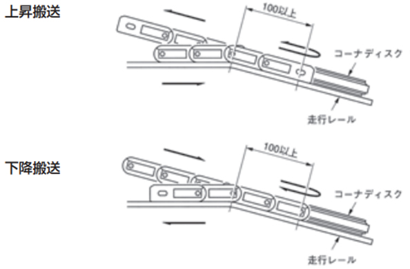
・上下搬送の曲線部
チェーンがコーナディスクから外れないようにコーナディスクに出入りする部分のチェーンとコーナディスクは同一平面になるようにします。
2-8. TPUH-BO形の水平コンベヤ設計
2-8-1. 水平搬送時のスプロケットとコーナディスク
水平搬送
(記号の説明)
- ・DO:水平搬送用スプロケット(コーナディスク)の外径(mm)
- ・R:チェーンの横曲り半径(mm)
- ・R1:チェーン外側走行レールの内周半径(mm)
注)
- 1. 水平搬送の場合チェーンの伸びを吸収する機構を設置してください。
- 2. 水平搬送でのスプロケットおよびコーナディスク巻付き時、チェーンがわずかに上下する場合があります。
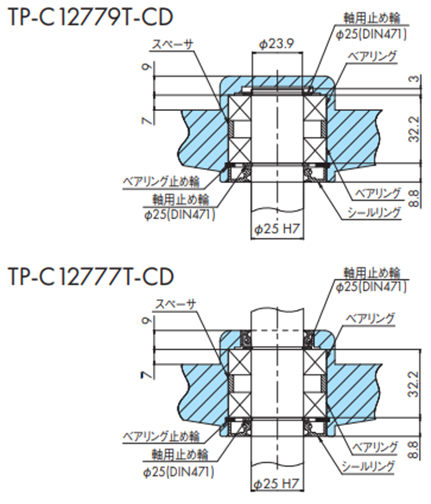
2-8-2. スプロケット、コーナディスクの軸部取付け
・水平搬送用スプロケット取付け
- 1. 水平搬送用スプロケットTP-C12781LT-SPRにキー溝の付いたハブTP-C12773T-HBを圧入してください。
- 2. Φ25のシャフト(キー付)にスプロケットを固定し、最後にM8のネジを組み込んでください。
・コーナディスクの取付け
2-9. プラクレセント®のコンベヤチェーン
走行レールの配置
配置スペースなどにより異なりますが、下記例を参考にしてください。
※ステンレストップチェーンTO形を使用する際に下記例を参考に走行レール配置する場合、チェーンの寸法をご確認ください。
・走行レールの設置例 (1)
・TOSP1143+コーナ部スプロケット使用の場合
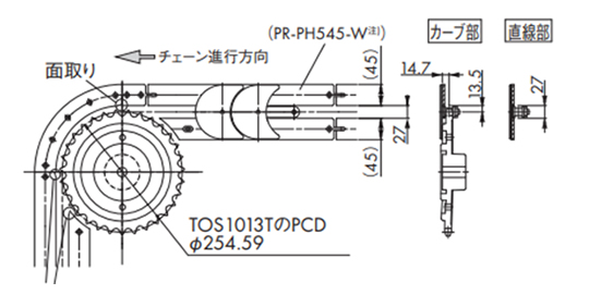
カーブドプラレールの入口部、出口直後の直線レールには、チェーンの引っかかりを防止するための「面取り」を施してください。
注)PR-PH545-Wをご検討の際は当社までお問合せください。
・走行レールの設置例 (2)
・TORP1143+コーナ部スプロケット使用の場合
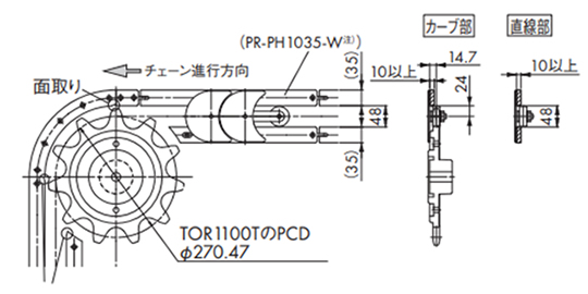
カーブドプラレールの入口部、出口直後の直線レールには、チェーンの引っかかりを防止するための「面取り」を施してください。
注)PR-PH1035-Wをご検討の際は当社までお問合せください。
・走行レールの設置例 (3)
・TORP1143+コーナ部カーブドプラレール使用の場合
カーブドプラレールの入口部、出口直後の直線レールには、チェーンの引っかかりを防止するための「面取り」を施してください。
注)PR-PH1035-Wをご検討の際は当社までお問合せください。
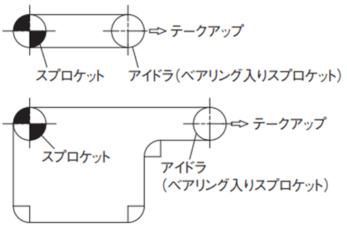
コンベヤレイアウトの注意事項
コンベヤの摩耗伸びや温度変化などによる伸びを吸収できるように、テークアップ機構を必ず設置してください。
下記例を参考ください。
2-10. コンベヤの継足し
コンベヤの機長が長くなると、チェーン張力が増大し強度が不足します。このような場合には、コンベヤを継足します。
コンベヤの継足しには、以下3つの方法がありますが、搬送物をスムーズに乗移りさせるためにはコンベヤの高さ関係が重要となります。
2-10-1. 平行渡し
平行して隣接した両コンベヤへガイドだけで載せ換える最も好ましい方法です。
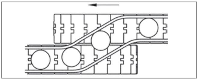
- 1. チェーンの高さは同一か送出し側のチェーンをわずかに高くする。
- 2. ガイドレールは搬送物をスムーズに案内出来るようになだらかにする。
2-10-2. 渡り板(デッドプレート)渡し
両コンベヤが直角に置かれた場合に渡り板(デッドプレート)により乗せ換える方法です。
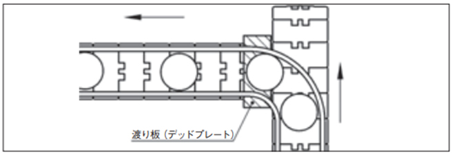
- 1. 渡り板は送出す側のチェーンの高さよりわずかに低くする。
- 2. 渡り板は搬送物がスムーズに流れるように角部に面取り加工する。
- 3. 受渡し側のチェーンの従動側コーダルアクションによる上下運動でチェーンと接触しないよう充分注意して取付けする。
2-10-3. 円板(ターンテーブル)渡し
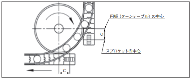
回転する円板(ターンテーブル)で積極的に搬送物を受け渡す方法。
ターンテーブルの高さ
- ・搬送側のチェーンの高さよりわずかに低くする。
・戻り側のチェーンの高さよりわずかに高くする。
ターンテーブルの外周に面取り加工を行う。
一般には駆動、従動スプロケットの中心近くにターンテーブルの中心を合わせますが、コーダルアクションの影響を避けるためには中心位置(C)だけ前方へ出すと上下運動の影響がなく、より安定します。
2-11. 耐熱・高速(KV)仕様トップチェーン使用上の留意点
2-11-1. 常温で使用する場合
- 1. 走行レール材質はスチールまたはスチール(硬質クロムメッキ+バフ仕上)を施したものや、ステンレス鋼(冷間圧延材)を推奨します。
- 2. 黒い摩耗粉が発生します。定期的に清掃してください。
- 3. スロースタート・スロー停止を行ってください。
2-11-2. 高温で使用する場合
- 1. 走行レール材質はステンレス製(冷間圧延材)を推奨します。
- 2. 走行レールの固定は熱膨張を考慮して一端のみ固定してください。また、走行レール間のスキマも熱膨張を考慮してください。
(参考:SUS304の線膨張係数...1.8×10-5/℃)
(例)ステンレス走行レールの固定と走行レール間のスキマ
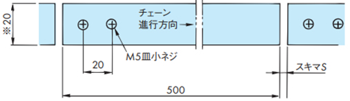
※印...TTP-KV、TPS-KV、TTUP-KV、TPU-KVの場合です。RSP35(40・60)-KVは上記表10を参照ください。
走行レール長さ500mmの場合のスキマS
| 使用温度 ℃ | 50 ~ 100 | 100 ~ 150 | 150 ~ 200 | 200 ~ 250 |
|---|---|---|---|---|
| スキマ S | 1.5 | 2 | 2.5 | 3 |
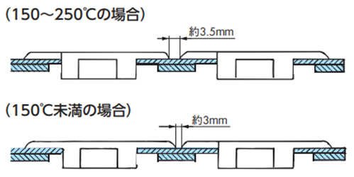
- 3. スプロケットは使用雰囲気温度150℃未満の場合はスチール製の標準スプロケットが使用できます。
150℃以上の場合は、特殊スプロケットを使用します。当社までご相談ください。 - 4. チェーンを多列で使用する場合はチェーンとチェーンのスキマは下記寸法としてください。
- 5. チェーンの熱膨張を吸収するため、テークアップが必要です。テークアップ調整は必ず、使用温度に上げてから行ってください。
温度を下げる時は、必ずテークアップを緩めてから行ってください。 - 6. 黒い摩耗粉が発生します。定期的に清掃してください。
- 7. 起動時は(インバータ制御などで)スロースタートで立上げてください。また停止時はスロー停止してください。
