技術資料 トップチェーン 選定
このページはプラスチックモジュラーチェーン(固定幅)・トップチェーン・プラブロックチェーンそれぞれの製品の共通ページです。
選定手順や注意事項等をご覧になりたい方は下記へお進みください。
製品シリーズの絞り込みや仮選定をご希望の方は
こちらをクリックしてください。
使用条件が決まっており詳細な選定をご希望の方は
こちらをクリックしてください。
トップチェーンの選定手順
下記手順に沿って、最も搬送条件に適したトップチェーンと走行レールの選定を行ってください。
(各項目をクリックすると本文にスクロールできます。)
注)低温・耐薬品(UPE)仕様を選定される場合は、プラブロックチェーンRSP80-UPE問合せシートをご記入いただき当社までお問合せください。
手順1. 搬送条件の確認
搬送条件の確認を行ってください。
搬送条件確認項目
| 1.搬送物 | (1)材質 |
|---|---|
| (2)1個当たりの質量 g/個 | |
| (3)形状 | |
| (4)寸法(縦×横×高さ)(直径Φ×高さ) mm | |
| (5)搬送方向 | |
| 2.搬送経路 | (1)直線搬送・曲線搬送 |
| (2)コンベヤ長さ m | |
| (3)コンベヤ幅 mm | |
| (4)搬送レイアウト | |
| (5)スペース m | |
| 3.搬送条件 | (1)搬送量 BPM・個 |
| (2)搬送間隔 mm | |
| (3)コンベヤ速度 m/min | |
| (4)潤滑の有無 | |
| (5)搬送物のストックの有無(アキュムレートの有無、割合)(有の場合、アキュムレートの長さ:m) | |
| 4.使用条件 | (1)温度 ℃ |
| (2)薬品、水、湿度などの腐食条件(各種液体に対する耐食性参照)(有の場合、液体名称) | |
| (3)ガラス破片、塗装屑、金属粉、砂などの摩耗促進物の有無 | |
| (4)紫外線照射の有無 |
2-(4)搬送レイアウト・その他メモ
手順2. チェーン仕様の選定
2-1. チェーン仕様の選定
表1を参照し、搬送物の材質から適切なトッププレート材質を選択してください。
注)
- 1. チェーンタイプおよび使用可能温度、条件は各商品ページを参照ください。
- 2. 耐食性は各種液体に対する耐食性を参照ください。
表1. トッププレート材質の選定表
| 搬送物 | トッププレート 材質 |
潤滑 | |||
|---|---|---|---|---|---|
| 無 | 有 | ||||
| 摩耗性介在物 | |||||
| 無 | 有 | 無 | 有 | ||
| ・ブリキ缶、アルミ缶、鉄缶、金属箔容器注)3 ・プラスチック、プラスチック被覆容器、紙容器注)4 |
ポリアセタール | C | × | A | D |
| ステンレス | D | C | B | A | |
| ・ガラスビン、ガラス製品、陶器類注)5 ・各種工業用部品注)6 |
ポリアセタール | D | × | B | × |
| ステンレス | C | C | A | A | |
注)
- 1. 「A」:特に推奨、「B」:推奨、「C」:可の中での推奨、「D」:可、「×」:不適当。
- 2. 食品や飲料の搬送ラインで抗菌・防カビ性能が必要な場合は抗菌・防カビ(MWS)仕様を選定してください。
- 3. ビール缶、ソフトドリンク缶、ふたと底が金属で側面がファイバのものなども含みます。
- 4. 牛乳、チーズ、アイスクリームなどの乳製品、菓子などのプラスチックやプラスチック被覆容器および紙容器など、石鹸、穀物などの紙板や紙底の製品も含みます。
- 5. 酒、食品、製薬、化粧品などに使われるガラスビン、ガラス容器も含みます。
- 6. 機械部品、型、鋳造品、鍛造品、メタル、ベアリング、ボルト、ナットなども含みます。
2-2. トッププレート幅の選定
一般的にトッププレートの幅は搬送物の幅よりも少し大きいものを選択します。
搬送物の幅が大きく、満足するトッププレート幅がない場合は、同じ幅のチェーンを多列で使用します。異なる幅のチェーンを多列で使用することもできますが、チェーンに作用する張力が不均等になり好ましくありません。
また、プラスチックモジュラーチェーンを使用することもできます。
・カット品のトッププレート端面形状
カット端面上部の面取り:約C0.5~0.8、四隅約C2面取りを施しています。
| 端面形状 |
|---|
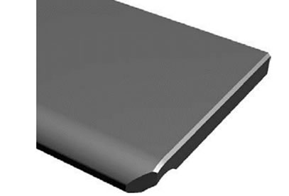 |
注)
- 1. 機械加工となります。
- 2. カタログに記載のないトッププレート幅を製作する場合も上記端面形状になります。
- 3. 打合せにより特殊端面形状も加工します。
- 4. トッププレート幅が小さい場合は面取りが異なる場合があります。
- 5. 機械加工によるトッププレート幅加工のため、本体チェーン刻印と形式が異なります。
手順3. 走行レール材質の選定
チェーン仕様から適切な走行レール材質を選択してください。
表2. 走行レール材質の選定表
| チェーン | 走行レール材質 | 潤滑 | |||
|---|---|---|---|---|---|
| 無 | 有 | ||||
| 摩耗性介在物 | |||||
| 無 | 有 | 無 | 有 | ||
| ステンレストップチェーン ・直線搬送用 ・曲線搬送用 |
ステンレス | D | D | B | B |
| スチール | D | C | B | A | |
| プラレール(Pレール) PLFレール |
A | × | A | × | |
| Mレール SJ-CNO |
A | × | × | × | |
| プラトップチェーン プラブロックチェーン プラスチックモジュラーチェーン(固定幅) ・直線搬送用 ・曲線搬送用 |
ステンレス | B | D | A | A |
| スチール | A | C | D | D | |
| プラレール(Pレール) | D | × | A | × | |
| PLFレール | B | × | A | × | |
| Mレール SJ-CNO |
A | × | × | × | |
注)
- 1. 「A」:特に推奨、「B」:推奨、「C」:可の中での推奨、「D」:可、「×」:不適当。
- 2. ステンレストップチェーンのラムダ仕様は潤滑無で使用してください。
- 3. 耐熱・高速(KV)仕様の場合は、常温ではステンレスまたはスチール製走行レールとし、高温(50℃を超える)ではステンレス製としてください。
- 4. 推奨金属走行レール=冷間圧延材。
- 5. スチールレールは油潤滑の場合を示しています。
プラレールの材質・外観色・特長
| 材質・外観色 | 特長 | |
|---|---|---|
| プラレール (Pレール) |
超高分子量ポリエチレン (外観色:白色または緑色) |
・最も一般的なレール ・削加工または押出成形品 ・プラスチックトップチェーンの場合、ウェット条件での使用推奨 ・吸水性が少なく、耐薬品性、耐衝撃性にも優れます。 |
| PLFレール | 低摩擦・耐摩耗性 超高分子量ポリエチレン (外観色:白色) |
・Pレールよりも低摩擦で耐摩耗性があるレール ・削加工または押出成形品 |
| Mレール SJ-CNO |
特殊ポリアミド (Mレール:外観色:青色) (SJ-CNO:外観色:紫色) |
・ドライ条件専用レール ・耐摩耗性があるレール ・削加工品 |
注)使用温度範囲
プラレール(Pレール)、PLFレール:-20℃~60℃
Mレール・SJ-CNO:-20℃~80℃
手順4. 係数の決定
表3~6の各係数は、当社内の実験データに基づいています。
使用条件や使用雰囲気、搬送物の形状や材質(仕様)、チェーンの汚れ方などによって差異が生じることがあります。各係数は手順5の張力計算に使用してください。
表3. トップチェーンと相手材の動摩擦係数(μ1、μ2)
| 相手材 | 潤滑状態 | トッププレート材質/仕様 | |||||||||||
|---|---|---|---|---|---|---|---|---|---|---|---|---|---|
| ステンレス 注)1 |
スチール | ポリアセタール | KV 注)2 | DIA MPD |
HTW | MF | HS | ||||||
| 普通仕様注)3 | 低摩擦仕様注)4 | CB | ALF | ||||||||||
| 走行レール 材質(μ1) |
ステンレス | 潤滑なし(ドライ) | 0.35 | 0.35 | 0.25 | 0.20 | - | 0.14 | 0.25 | 0.30 | 0.35 | 0.27 | 0.25 |
| 水潤滑 | 0.35 | - | 0.25 | 0.20 | - | 0.14 | 0.25 | - | 0.35 | - | - | ||
| 石鹸水潤滑 | 0.20 | - | 0.15 | 0.15 | - | 0.11 | 0.16 | - | 0.20 | - | - | ||
| 油潤滑 | 0.20 | 0.20 | - | - | - | - | - | - | - | - | - | ||
| スチール | 潤滑なし(ドライ) | 0.35 | 0.35 | 0.25 | 0.17 | - | 0.14 | 0.25 | 0.30 | 0.35 | 0.27 | 0.25 | |
| 水潤滑 | - | - | - | - | - | - | - | - | - | - | - | ||
| 石鹸水潤滑 | - | - | - | - | - | - | - | - | - | - | - | ||
| 油潤滑 | 0.20 | 0.20 | - | - | - | - | - | - | - | - | - | ||
| プラレール (Pレール) Mレール注)5 |
潤滑なし(ドライ) | 0.25 | 0.25 | 0.25 | 0.20 | 0.20 | 0.15 | - | 0.30 | 0.30 | 0.27 | - | |
| 水潤滑 | 0.25 | - | 0.25 | 0.20 | 0.20 | 0.15 | - | - | 0.30 | - | - | ||
| 石鹸水潤滑 | 0.15 | - | 0.15 | 0.13 | - | 0.11 | - | - | 0.20 | - | - | ||
| 油潤滑 | 0.15 | 0.15 | - | - | - | - | - | - | - | - | - | ||
| SJ-CNO 注)5 | 潤滑なし(ドライ) | 0.20 | 0.20 | 0.20 | 0.15 | - | 0.13 | - | 0.30 | 0.24 | 0.22 | 0.25 | |
| 水潤滑 | 0.20 | - | 0.20 | 0.15 | - | 0.13 | - | - | 0.24 | - | - | ||
| 石鹸水潤滑 | 0.15 | - | 0.12 | 0.12 | - | 0.11 | - | - | 0.20 | - | - | ||
| 油潤滑 | 0.15 | 0.15 | - | - | - | - | - | - | - | - | - | ||
| PLFレール | 潤滑なし(ドライ) | - | - | 0.18 | 0.14 | - | 0.12 | - | - | - | - | - | |
| 水潤滑 | - | - | 0.18 | 0.14 | - | 0.12 | - | - | - | - | - | ||
| 石鹸水潤滑 | - | - | 0.12 | 0.12 | - | 0.11 | - | - | - | - | - | ||
| 油潤滑 | - | - | - | - | - | - | - | - | - | - | - | ||
| 搬送物 材質 (μ2) |
金属缶 | 潤滑なし(ドライ) | 0.35 | - | 0.25 | 0.20 | 0.19 | 0.14 | 0.23 | 0.30 | 0.35 | 0.28 | 0.22 |
| 水潤滑 | 0.35 | - | 0.25 | 0.20 | 0.19 | 0.14 | 0.23 | - | 0.35 | - | - | ||
| 石鹸水潤滑 | 0.20 | - | 0.14 | 0.13 | - | 0.11 | 0.15 | - | 0.20 | - | - | ||
| 油潤滑 | - | - | - | - | - | - | - | - | - | - | - | ||
| ガラスビン | 潤滑なし(ドライ) | 0.25 | - | 0.22 | 0.14 | 0.12 | 0.10 | 0.18 | 0.25 | 0.22 | 0.25 | - | |
| 水潤滑 | 0.25 | - | 0.22 | 0.14 | 0.12 | 0.10 | 0.18 | - | 0.22 | - | - | ||
| 石鹸水潤滑 | 0.20 | - | 0.14 | 0.14 | - | 0.10 | 0.15 | - | 0.10 | - | - | ||
| 油潤滑 | - | - | - | - | - | - | - | - | - | - | - | ||
| プラ容器 | 潤滑なし(ドライ) | 0.35 | - | 0.25 | 0.17 | 0.16 | 0.13 | 0.20 | 0.30 | 0.30 | 0.28 | 0.20 | |
| 水潤滑 | 0.35 | - | 0.25 | 0.17 | 0.16 | 0.13 | 0.20 | - | 0.30 | - | - | ||
| 石鹸水潤滑 | 0.20 | - | 0.15 | 0.13 | - | 0.11 | 0.15 | - | 0.20 | - | - | ||
| 油潤滑 | - | - | - | - | - | - | - | - | - | - | - | ||
| 紙パック | 潤滑なし(ドライ) | 0.40 | - | 0.31 | 0.29 | 0.29 | 0.22 | 0.35 | 0.38 | 0.35 | 0.38 | 0.32 | |
| 水潤滑 | 0.40 | - | 0.31 | 0.29 | 0.29 | 0.22 | 0.35 | - | - | - | - | ||
| 石鹸水潤滑 | 0.20 | - | 0.20 | 0.20 | - | 0.12 | 0.20 | - | - | - | - | ||
| 油潤滑 | - | - | - | - | - | - | - | - | - | - | - | ||
注)
- 1. ステンレストップチェーンのラムダ仕様は潤滑無で使用してください。
- 2. 耐熱・高速(KV)仕様は常温での摩擦係数です。高温(50℃を超える)の場合は動摩擦係数0.35を適用してください。また耐熱・高速(KV150)仕様はドライ条件専用です。
- 3. 対象:普通仕様、耐薬品(Y)仕様、導電(E)仕様、耐衝撃(DIY)仕様、金属検知(MPW)仕様、耐酸(AR)仕様、耐紫外線(UVR)仕様、プラクレセント。
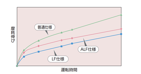
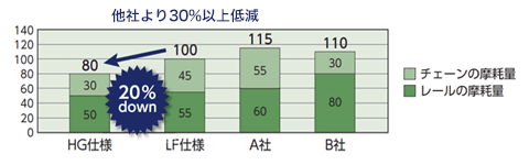
- 4. 対象:低摩擦・耐摩耗(LFW・LFG・LFB)仕様、低摩擦(NLF・WR)仕様、低摩擦・耐摩耗(HG)仕様、抗菌・防カビ(MWS)仕様。
- 5. Mレール、SJ-CNOはドライ条件専用走行レールです。
- 6. 水潤滑時のステンレスピンタイプはプラピンタイプよりも摩耗伸びが早くなります。
- 7. 搬送物の種類によっては、(μ2)の値より大きくなり、吸着現象が生じる場合があります。動摩擦係数は搬送毎に測定をおすすめします。
表4. 搬送物とプラローラとの転がり摩擦係数(μ3)
| 対象チェーン | 転がり摩擦係数 |
|---|---|
| アキュムレーションチェーンTTPDH-LBP形 カーブドアキュムレーションチェーンTPUS-LBP形、TPUS-Y-LAP-LFB-MFR形 |
0.10 |
| カーブドアキュムレーションチェーンTPUS-Y-LAP形、TP-30UTW-LAP形、TP-36UTW-LAP形 | 0.07 |
表5.曲線用走行レール使用時の角度係数(αL)、長さ係数(αS)
| トッププレート材質 | 潤滑状態 | 横曲り角度 | |||||||
|---|---|---|---|---|---|---|---|---|---|
| 30° | 60° | 90° | 120° | 150° | 180° | ||||
| 角度係数(αL) | ステンレスまたはスチール | 潤滑なし・水潤滑 | 1.20 | 1.45 | 1.75 | 2.10 | 2.50 | 3.00 | |
| 石鹸水潤滑 | 1.10 | 1.25 | 1.35 | 1.50 | 1.70 | 1.85 | |||
| 油潤滑 | 1.10 | 1.25 | 1.35 | 1.50 | 1.70 | 1.85 | |||
| ポリアセタール | 普通仕様注)3 | 潤滑なし・水潤滑 | 1.15 | 1.30 | 1.50 | 1.70 | 1.90 | 2.20 | |
| 石鹸水潤滑 | 1.10 | 1.15 | 1.25 | 1.35 | 1.50 | 1.60 | |||
| 低摩擦仕様注)4 | 潤滑なし・水潤滑 | 1.10 | 1.25 | 1.35 | 1.50 | 1.70 | 1.85 | ||
| 石鹸水潤滑 | 1.10 | 1.15 | 1.25 | 1.35 | 1.50 | 1.60 | |||
| CB | 潤滑なし・水潤滑 | 1.10 | 1.25 | 1.35 | 1.50 | 1.70 | 1.85 | ||
| 石鹸水潤滑 | - | - | - | - | - | - | |||
| ALF | 潤滑なし・水潤滑 | 1.10 | 1.15 | 1.25 | 1.35 | 1.50 | 1.60 | ||
| 石鹸水潤滑 | 1.05 | 1.10 | 1.20 | 1.25 | 1.35 | 1.40 | |||
| KV注)2 | 潤滑なし・水潤滑 | 1.15 | 1.30 | 1.50 | 1.70 | 1.90 | 2.20 | ||
| 石鹸水潤滑 | 1.10 | 1.20 | 1.30 | 1.40 | 1.50 | 1.65 | |||
| DIA,MPD | 潤滑なし(ドライ) | 1.15 | 1.35 | 1.60 | 1.85 | 2.20 | 2.55 | ||
| HTW | 潤滑なし・水潤滑 | 1.20 | 1.45 | 1.75 | 2.10 | 2.50 | 3.00 | ||
| 石鹸水潤滑 | 1.10 | 1.25 | 1.35 | 1.50 | 1.70 | 1.85 | |||
| MF | 潤滑なし(ドライ) | 1.15 | 1.35 | 1.55 | 1.75 | 2.05 | 2.35 | ||
| HS | 潤滑なし(ドライ) | 1.15 | 1.30 | 1.50 | 1.70 | 1.90 | 2.20 | ||
| 長さ係数(αS) | 0.5 | 1 | 1.6 | 2.1 | 2.6 | 3.1 | |||
注)
- 1. チェーンと走行レールが摺動する曲線コンベヤでは潤滑を推奨します。特に90°を超える横曲り角度の場合は、比較的短期間でチェーンまたは走行レールが偏摩耗し、チェーンが浮上がる可能性があります。潤滑できない場合はコーナディスクによる横曲りを検討ください。
- 2. 耐熱・高速(KV)仕様の数値は常温の場合です。高温(50°を超える)の場合は、スチールまたはステンレスの潤滑なし・水潤滑の数値を適用してください。
- 3. 対象:普通仕様、耐薬品(Y)仕様、導電(E)仕様、耐衝撃(DIY)仕様、金属検知(MPW)仕様、耐紫外線(UVR)仕様、プラクレセント。
- 4. 対象:低摩擦・耐摩耗(LFW・LFG・LFB)仕様、低摩擦(NLF・WR)仕様、低摩擦・耐摩耗(HG)仕様、抗菌・防カビ(MWS)仕様。
表6. コーナディスク使用時の角度係数(αc)
| 対象チェーン | 角度係数 (αc) |
|---|---|
|
TPUSR550形 TPUSR826形 TPUH-BO形 TPUN555形 TPUN550-LH形 TPUN535-LH形 TP-UB36形 TP-50UNS形 (D76を含む) |
ベアリング付コーナディスク:1.1 ベアリングなしコーナディスク:1.15 |
注)
- 1. αcはコーナディスクを使用したチェーンの曲線搬送に用いる係数で、横曲り角度に関係なく一定です。
- 2. プラクレセントTOS形はコーナ部ではスプロケットを使用します。スプロケット軸部のベアリングがある場合は上表の値を適用ください。
手順5. チェーン張力および所要動力の計算
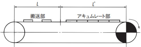
5-1. 直線搬送のFの計算
注)SI単位と重力単位
計算式はSI単位と、重力単位を併記しています。重力単位で張力Fを計算する場合、重力単位の重量(kgf)はSI単位の質量(kg)と同一の数値です。
記号の説明
- F = チェーンに作用する張力 kN{kgf}
- m1 = チェーン概略質量 (kg/m)
- L = 搬送部の長さ (m)
- m2 = 搬送部の搬送物質量 (kg/m)
- L' = アキュムレート部の長さ (m)
- m3 = アキュムレート部の搬送物質量 (kg/m)
- μ1 = チェーンと走行レールの動摩擦係数 (表3参照)
- μ2 = アキュムレート部のチェーンと搬送物の動摩擦係数 (表3参照)
- μ3 = プラローラと搬送物の転がり摩擦係数 (表4参照)
- αL = 曲線用走行レール使用時の角度係数 (表5参照)
- αC = コーナディスク使用時の角度係数 (表6参照)
- αS = 長さ係数 (表5参照)
- θ = 傾斜角度 (度)
- r = 横曲り半径 (m)
- P = 所要動力 (kW)
- V = チェーン速度 (m/min)
- η注) = 駆動部の伝達機械効率
注)伝達機械効率は、使用される駆動装置をご確認ください。
SI単位(kN)
チェーンに作用する張力
F = 9.80665 × 10⁻³ { (2.1m1 + m2) L・μ1 + (2.1m1 + m3) L'・μ1 + m3・L'・μ2 }
所要動力
P = F・V 60η
重力単位(kgf)
チェーンに作用する張力
F = (2.1m1 + m2) L・μ1 + (2.1m1 + m3) L'・μ1 + m3・L'・μ2
所要動力
P = F・V 6120η
注)アキュムレーションチェーン(TTPDH-LBP形など)をご使用の場合は上式のμ2をμ3に変えて計算してください。
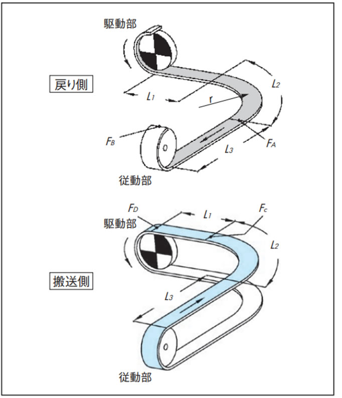
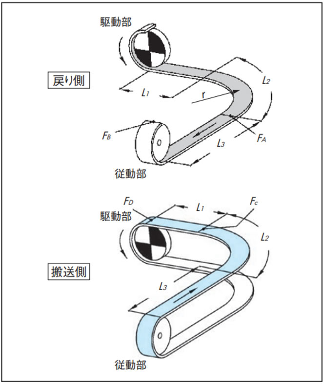
5-2. 曲線搬送(曲線部1箇所)のFの計算
基本的には、直線搬送の場合と同様です。コーナ部の作用張力は角度係数により補正します。
下図の搬送経路について計算例を示します。チェーンと走行レールが摺動する曲線搬送では潤滑されることを推奨します。特に90°を超える横曲り角度の場合は、比較的短期間でチェーンまたは走行レールが偏摩耗し、チェーンが浮上がる可能性があります。潤滑できない場合はコーナディスクによる横曲りを検討ください。
F = 9.80665 × 10⁻³ ・FD (kN)
戻り側張力
[A部張力:FA]
FA = m1(L1 + L2) μ1・αL 90°
L2 = r × αS 90°
[B部張力:FB]
FB = 1.1 ×(FA + m1・L3・μ1)
搬送側張力
[C部張力:FC]
FC ={FB + (m1 + m2) (L2 + L3) μ1 + m3 (L2 + L3) μ2}・αL 90°
L2 = r × αS 90°
[D部張力:FD]
FD = FC + {(m1 + m2) L1・μ1 + m3・L1・μ2}
注
- 1. カーブドアキュムレーションチェーン(TPUS-LBP形など)をご使用の場合は上式のμ2をμ3に変えて計算してください。
- 2. コーナ部にコーナディスクを使用する場合は、角度係数αLの代わりにコーナディスク角度係数αCをご使用ください。
5-3. 曲線搬送(曲線部2箇所)のFの計算
曲線部を走行レールなどで摺動させる場合は、90度カーブ2箇所までとしてください。チェーンの脈動の原因となります。
より多くの曲線部を設置したい場合は、コンベヤを分割するか、コーナディスクを用いた方式を検討してください。
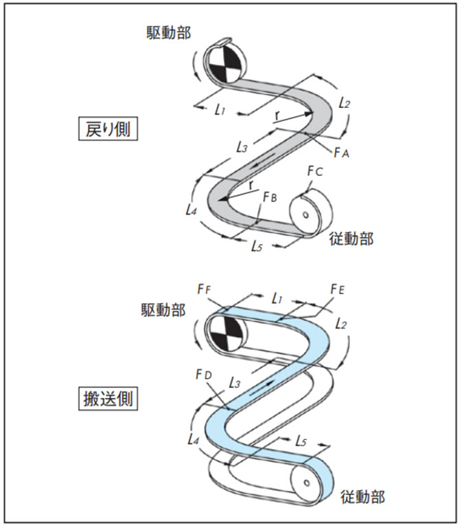
F = 9.80665 × 10⁻³ ・FF (kN)
戻り側張力
[A部張力:FA]
FA = m1(L1 + L2) μ1・αL 90°
L2 = r × αS 90°
[B部張力:FB]
FB = {FA + m1(L3 + L4) μ1} αL 90°
L4 = r × αS 90°
[C部張力:FC]
FC = 1.1 × (FB + m1・L5・μ1)
搬送側張力
[D部張力:FD]
FD = {FC + (m1 + m2) (L4 + L5) μ1 + m3(L4 + L5) μ2}・αL 90°
L4 = r × αS 90°
[E部張力:FE]
FE = {FD + (m1 + m2) (L2 + L3) μ1 + m3(L2 + L3) μ2}・αL 90°
L2 = r × αS 90°
[F部張力:FF]
FF = FE + (m1 + m2) L1μ1 + m3・L1・μ2
注
- 1. カーブドアキュムレーションチェーン(TPUS-LBP形など)をご使用の場合は上式のμ2をμ3に変えて計算してください。
- 2. コーナ部にコーナディスクを使用する場合は、角度係数αLの代わりにコーナディスク角度係数αCをご使用ください。
5-4. 曲線搬送(水平駆動)のFの計算
| 適用チェーン | TPUH-BO形(水平搬送時)、 プラクレセント(TORP形、TOSP形)、 ステンレストップチェーン(TO形、TU形) |
|---|
基本的には、直線搬送の場合と同様です。コーナ部の作用張力は角度係数により補正します。
下図の搬送経路について計算例を示します。
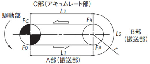
F = 9.80665 × 10⁻³ ・FC (kN)
[A部張力:FA] FA = (m1 + m2)・L1・μ1
[B部張力:FB] FB = {FA + (m1 + m2)・L2・μ1}・αC L2 = r・αS 180°
[C部張力:FC] FC = FB + (m1 + m3)・L1・μ1 + m3・L1・μ2
5-5. TTUP(T)-M形、TTUPM838H形曲線搬送(曲線部1ヵ所)のFの計算
表7の係数は、当社内の実験データに基づいています。使用条件、搬送物の形状や材質(仕様)によって、差異が生じることがあります。
各係数は張力計算にご使用ください。
F = 9.80665 × 10⁻³ ・FD (kN)
戻り側張力
[A部張力:FA]
FA = m1(L1 + L2) μ1・αL 90°
L2 = r × αS 90°
[B部張力:FB]
FB = 1.1 ×(FA + m1・L3・μ1)
搬送側張力
[C部張力:FC]
FC = {FB + (m1 + m2) L2・(μ1 + μ4) + (m1 + m2)・L3・μ1 + m3
(L2 + L3)・μ2} × αL 90°
L2 = r × αS 90°
[D部張力:FD]
FD = FC + {(m1 + m2) L1・μ1 + m3・L1・μ2}
表7.マグネット係数(μ4)
| マグネット係数 | ||
|---|---|---|
| 潤滑状態 | 潤滑なし・水潤滑 | |
| トッププレート材質 | CB | 0.47 |
| ALF | ||
| HG | ||
5-6. 傾斜搬送のFの計算
傾斜制限は、速度・搬送物・重心・質量・条件などの影響で正確に角度を決めることは困難です。
表8に目安を表示しますがテストを行うことが必要です。
表8. 傾斜搬送角度の目安
| チェーン材質 | 潤滑なし(ドライ) | 石鹸水潤滑 | 油潤滑 |
|---|---|---|---|
| スチール系 | 10度 | - | 6度 |
| 普通仕様(ポリアセタール) | 5度 | 3度 | - |
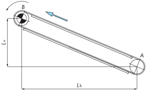
F = 9.80665 × 10⁻³ ・FB (kN)
戻り側張力
[A部張力:FA]
FA = 1.1m1 (Lh・μ1 - Lv)
FA < 0の場合は、FA = 0
チェーン張力
F = FB
搬送側張力
[B部張力:FB]
FB = FA + {(m1 + m2) (Lh・μ1 + Lv)}
手順6. チェーン形式の決定
チェーンに作用する張力(F)よりも大きな最大許容張力のトップチェーンを選定します。
チェーンの最大許容張力は、能力線図を参考にコンベヤ速度および使用雰囲気温度を加味して算出してください。
能力線図は各製品ページを参照ください。
F ≦ チェーンの最大許容張力(速度と温度を加味)
最大許容張力が不足している場合は、トッププレート幅を狭くしてチェーンの本数を多くする、もしくは短いコンベヤを継ぎたす方法があります。
または、最大許容張力の大きいチェーンを選択する方法もあります。
コンベヤの使用環境も考慮してチェーン形式を決定してください。