技術資料 ドライブチェーン ローラチェーンの選定
6. 許容張力選定法
最大許容張力を使用して行う選定法です。
1. 速度の考慮
本選定法は、表1に示す速度内にてローラチェーンを使用する場合の選定法です。表中の上限速度以上で使用される場合は、一般選定法で選定を行なってください。
| ピッチ mm |
上限速度 m/min |
|---|---|
| 12.70未満 | 120 |
| 12.70 | 100 |
| 15.875 | 90 |
| 19.05 | 80 |
| 25.40 | 70 |
| 31.75 | 60 |
| 38.10 | 50 |
| 44.45 | 50 |
| 50.80 | 50 |
| 57.15 | 40 |
| 63.50 | 40 |
| 76.20 | 40 |
| 101.60 | 30 |
| 127.00 | 30 |
プラコンビチェーンの上限速度は70m/minとなります。
2. 衝撃の考慮
衝撃の大きな伝動、特に負荷の大きな伝動や横荷重が作用する恐れのある伝動など、過酷な条件の場合にはF形継手リンクや2ピッチ形オフセットリンクをご使用ください。
3. 継手リンクとオフセットリンクの強度
表2および表3に示すローラチェーンにM形継手リンクやオフセットリンクを使用するときは、最大許容張力に表中の割合を乗します。
| RSローラチェーン | RS15, RS25, RS37, RS38, RS41, BF25-H |
80% |
| RSローラチェーン BS/DIN規格 |
RF06B, RS56B, RS56B |
80% |
| 耐寒ローラチェーン KT仕様 |
全サイズ | 80% |
| オフセットリンク | |||
|---|---|---|---|
| 1ピッチ | 2ピッチ | 4ピッチ | |
| RSローラチェーン | 65% | 100% | - |
| RSローラチェーン BS/DIN規格 |
60% | 60% | - |
| スーパチェーン | - | - | 85% |
| RSローラチェーン NP仕様 |
65% | - | - |
| RSローラチェーン NEP仕様・APP仕様 |
65% | - | - |
| 低騒音チェーン | 65% | - | - |
4. スプロケットの考慮
強力ドライブチェーンを使用される場合、チェーン張力が大きくなります。そのため、市販の鋳鉄製スプロケットでは、リブやハブの強度が不足する場合があります。材質はS35C相当以上を採用ください。RSスプロケットは強力ドライブチェーンに対応した強度を備えています。強力ドライブチェーンには歯先に硬化処理を行ったものを採用ください。
許容張力選定法による選定例
条件
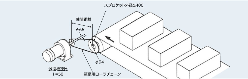
| 使用機械 | コンベヤ駆動 |
| 搬送物質量M | 6000kg |
| 搬送物速度Vℓ | 30m/min |
| コンベヤロール外径 | 380mm |
| ベルト厚さ | 10mm |
| コンベヤロール回転トルク | 3.3kN・m{337kgf・m} |
| モータ諸元 |
|
| 減速機減速比 | 1/50 (i = 50) |
| 駆動軸 | 軸径 Φ66mm |
| 従動軸 | 軸径 Φ94mm |
| 軸間距離 | 500mm |
| 従動スプロケット外径 | ≦400mm |
| 始動頻度 | 10回/日 |
| 衝撃の種類 | 多少の衝撃を伴う。 |
| ソフトスタート・ストップ | なし |
| SI単位 |
|---|
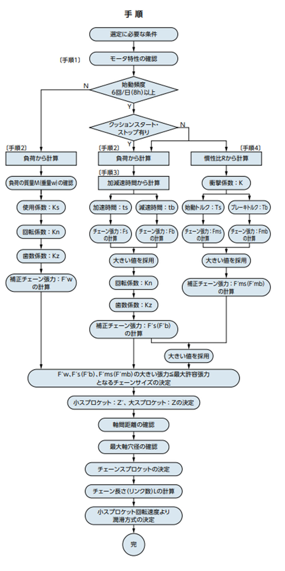
手順1 モータ特性の確認・定格トルク ・始動トルク ・最大(停動)トルク ・ブレーキトルク ・モータ慣性モーメント 手順2 負荷から計算従動軸回転数 駆動軸回転数 チェーン減速比 = 23.9 36 = 1 1.51 従動スプロケットのPCD d2 = 400mmとすると チェーンの仮選定を行います。 多少の衝撃を伴う.......使用係数 Ks = 1.3 仮補正チェーン張力 = Fw × Ks = 16.5 × 1.3 = 21.5(kN) 最大許容張力30.4kNのRS120-1を仮選定します。 従動スプロケット外径 < 400mmより31T 駆動スプロケット歯数 = 31 1.51 = 21T PCD d = 255.63(mm) チェーン速度 =
P × Z'× n
1000
=
38.1 × 21 × 36
1000
小スプロケット回転速度 36r/min・回転係数 Kn = 1.03 小スプロケット歯数 21T....歯数係数 Kz = 1.10 チェーン張力 Fw = コンベヤロール回転トルク × 1000 ×
2
d2
補正チェーン張力 F'w = Fw × Ks × Kn × Kz RS120-1最大許容張力30.4kNの使用は可能です。 搬送物速度の確認(選定条件 30m/min) Vℓ = n2 ×
(コンベヤロール外径 + 2 × ベルト厚さ) × π
1000
手順3 加減速時間から計算手順2の計算で小スプロケット(減速機出力軸スプロケット)はRS120の21Tとなったので、以下の計算も同一ピッチ、歯数で選定します。 加減速時間が既知ならば、その値を使用して計算します。ここでは未知の前提で計算します。 作用トルク Tm = Ts + Tmax 2 = 0.116 + 0.122 2 = 0.119(kN・m) 負荷トルク Tℓ = Fw ×
d
2 × 1000 × i
= 17.5 ×
255.63
2 × 1000 × 50
モータ軸換算 負荷側の慣性モーメント Iℓ モータの慣性モーメント Im = 0.088(kg・m2)
モータの加速時間
モータの減速時間 tb < tsより、加速時のチェーン張力Fsより減速時のチェーン張力Fbの方が大きいので、以下これを採用します。 減速度 減速時のチェーン張力
補正チェーン張力 同等のPCDを有するRS140 18T(外径279mm d1 = 255.98)と27T(外径407mm d2 = 382.88)で検討すると、条件の従動スプロケット外径≦400mmに抵触するので使用不可です。
チェーン減速比は必要な3623.9から2618となり、 RS140-1は最大許容張力40.2kNのため使用不可です。 RS140-SUP-1は最大許容張力53.9kNのため使用可能です。 スプロケット軸穴径18Tで最大89mm、26Tで最大103mmですので、 軸間距離500mmですので、スプロケット歯数は18T(d1 = 255.98)と 手順4 慣性比Rから計算慣性比R = Iℓ Im = 0.044 0.088 = 0.5 伝動装置に遊びがあるので....衝撃係数 K = 1.0 始動トルク Ts = 0.116(kN・m) 始動トルクによるチェーン張力 ブレーキトルク Tb = 0.116(kN・m) ブレーキトルクによるチェーン張力 Fmb > Fmsより、大きい方のFmbを採用します。 補正チェーン張力
(1)、(2)、(3)を比較すると(3)が一番大きい補正チェーン張力となります。 F'mb = 61.7(kN)ですので、RS120-3(最大許容張力76.0kN)、 軸間距離500mmですので、スプロケット歯数は21T(d1 = 255.63)と 同等のPCDを有するRS160 15T(外径269mm d1 = 244.33)と RS160-1は最大許容張力53.0kNのため使用不可です。 RS160-SUP-1は最大許容張力70.6kNのため使用可能です。 スプロケット軸穴径15Tで最大95mm、23Tで最大118mmですので、 軸間距離500mmですので、スプロケット歯数は15T(d1 = 244.33)と |
| {重力単位} |
|---|
手順1 モータ特性の確認・定格トルク ・始動トルク ・最大(停動)トルク ・ブレーキトルク ・モータのGD2 手順2 負荷から計算従動軸回転数 駆動軸回転数 チェーン減速比 = 23.9 36 = 1 1.51 従動スプロケットのPCD d2 = 400mmとすると チェーンの仮選定を行います。 多少の衝撃を伴う.......使用係数 Ks = 1.3 仮補正チェーン張力 = Fw × Ks = 1690 × 1.3 = 2200(kgf) 最大許容張力3100kgfのRS120-1を仮選定します。 従動スプロケット外径 < 400mmより31T 駆動スプロケット歯数 = 31 1.51 = 21T PCD d = 255.63(mm) チェーン速度 =
P × Z'× n
1000
=
38.1 × 21 × 36
1000
小スプロケット回転速度 36r/min・回転係数 Kn = 1.03 小スプロケット歯数 21T....歯数係数 Kz = 1.10 チェーン張力 Fw = コンベヤロール回転トルク × 1000 ×
2
d2
補正チェーン張力 F'w = Fw × Ks × Kn × Kz RS120-1最大許容張力3100kgfの使用は可能です。 搬送物速度の確認(選定条件 30m/min) Vℓ = n2 ×
(コンベヤロール外径 + 2 × ベルト厚さ) × π
1000
手順3 加減速時間から計算手順2の計算で小スプロケット(減速機出力軸スプロケット)はRS120の21Tとなったので、以下の計算も同一ピッチ、歯数で選定します。 加減速時間が既知ならば、その値を使用して計算します。ここでは未知の前提で計算します。 作用トルク Tm = Ts + Tmax 2 = 11.9 + 12.5 2 = 12.2(kgf・m) 負荷トルク Tℓ = Fw ×
d
2 × 1000 × i
= 1790 ×
255.63
2 × 1000 × 50
モータ軸換算 負荷側のGD2 モータのGD2 GD2m = 0.352(kgf・m2) モータの加速時間
モータの減速時間 tb < tsより、加速時のチェーン張力Fsより減速時のチェーン張力Fbの方が大きいので、以下これを採用します。 減速度 減速時のチェーン張力
補正チェーン張力 同等のPCDを有するRS140 18T(外径279mm d1 = 255.98)と27T(外径407mm d2 = 382.88)で検討すると、条件の従動スプロケット外径≦400mmに抵触するので使用不可です。
チェーン減速比は必要な3623.9から2618となり、 RS140-1は最大許容張力4100kgfのため使用不可です。 RS140-SUP-1は最大許容張力5500kgfのため使用可能です。 スプロケット軸穴径18Tで最大89mm、26Tで最大103mmですので、 軸間距離500mmですので、スプロケット歯数は18T(d1 = 255.98)と 手順4 慣性比Rから計算慣性比R = GD2ℓ GD2m = 0.176 0.352 = 0.5 伝動装置に遊びがあるので....衝撃係数 K = 1.0 始動トルク Ts = 11.9(kgf・m) 始動トルクによるチェーン張力 ブレーキトルク Tb = 11.9(kgf・m) ブレーキトルクによるチェーン張力 Fmb > Fmsより、大きい方のFmbを採用します。 補正チェーン張力
(1)、(2)、(3)を比較すると(3)が一番大きい補正チェーン張力となります。 F'mb = 6330(kgf)ですので、RS120-3(最大許容張力7550kgf)、 軸間距離500mmですので、スプロケット歯数は21T(d1 = 255.63)と 同等のPCDを有するRS160 15T(外径269mm d1 = 244.33)と RS160-1は最大許容張力5400kgfのため使用不可です。 RS160-SUP-1は最大許容張力7200kgfのため使用可能です。 スプロケット軸穴径15Tで最大95mm、23Tで最大118mmですので、 軸間距離500mmですので、スプロケット歯数は15T(d1 = 244.33)と |
選定結果
| 条件 | 手順 | 形番 | スプロケット | リンク数 | 潤滑形式 |
|---|---|---|---|---|---|
| 始動頻度6回未満 | 手順2 | RS120-1 | 21T×31T | 54リンク | AII |
| 始動頻度6回以上 クッションスタートあり。 |
手順3 | RS120-2 | 21T×31T | 54リンク | AII |
| RS140-SUP-1 | 18T×26T | 46リンク | B | ||
| 始動頻度6回以上 クッションスタートなし。 |
手順3 手順4 |
RS120-3 | 21T×31T | 54リンク | AII |
| RS120-SUP-2 | B | ||||
| RS160-SUP-1 | 15T×23T | 40リンク | B |
- 注)1.潤滑形式:各チェーンのサイズ、仕様の伝動能力表でご確認いただけます。
- 2.全て軸間距離の調整は必要です。
