技術資料 ピンギヤドライブユニット
選定手順
ピンギヤドライブユニットのピッチ円直径 仮選定
| 回転運動時: | 回転装置のサイズからピンホイールのピッチ円直径を仮選定してください。減速比からピンギヤのピッチ円直径を仮選定してください。 |
| 直線運動時: | 装置レイアウトからピンギヤのピッチ円直径を仮選定してください。 |
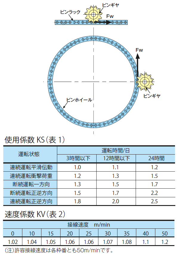
負荷接線荷重 Fw の計算
負荷条件からピンホイールあるいはピンラックに作用する負荷接線荷重Fwを計算してください。
補正接線荷重 Ft の計算
運転条件から使用係数KS(表1)を、接線速度から速度係数KV(表2)を求め、負荷接線荷重FWに乗じて補正接線荷重FTを求めてください。
ピンギヤドライブユニットの枠番選定
ピンラックあるいはピンホイールの各枠番ごとの許容接線荷重FPと補正接線荷重FTから下記条件を満足するピンギヤドライブユニットの枠番を選定してください。
形番の選定
| ピンホイール: | 選定した枠番と仮選定ピンホイールのピッチ円直径から一番近いピッチ円直径のピンホイールのローラ数を選んでください。 |
| ピンラック: | 選定した枠番と走行距離(または移動距離)よりラックのローラ数を求めてください。 |
| ピンギヤ: | 選定した枠番と仮選定したピンギヤのピッチ円直径から一番近いピッチ円直径のピンギヤの歯数を選び、形番を決めます。 |
| ※ギヤ歯数は使用できる範囲に制限があります。歯数が不足する場合は歯数を上げて再選定してください。 | |
[クリックで拡大]
潤滑
運転前には、必ず全てのローラ外周面に極圧系グリースを塗布してください。ピンホイールあるいはピンラックのローラ内面にはあらかじめ潤滑用のグリースを塗布しています。
水中使用などのように潤滑用グリースが使用できない雰囲気、あるいは130℃以上の高温雰囲気でご使用になる場合は別途ご相談ください。
特殊バックラッシ仕様 (標準の許容接線荷重とは異なります)
●大バックラッシ仕様
バックラッシを大きくすることで容易な据付が可能です。
●小バックラッシ仕様
バックラッシを小さくすることが可能です。(標準バックラッシの2/3 対応枠番:PDU020~PDU120)
取付方法
フラット・ホイール
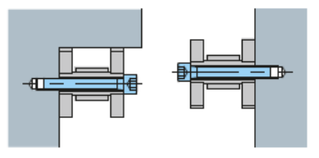
中空ピンを使用していますので、この穴を利用して側面を相手装置にボルトで固定できます。取付に際して、一方向の面にストッパ又はガイドを設けて位置決め可能です。
アングル
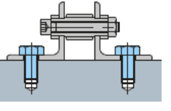
アングル形の直線ラックは、ボルト締付用の穴を用いて脚面を相手装置に固定できます。
取付ボルト位置
ボルトはセグメントの両端とその間を等配置で最小取付数(下記参照)以上で取付けてください。
■1セグメントの最小取付ボルト本数(水平取付の場合)
| 仕様 | 枠番 | 取付ボルト サイズ | 最小 取付数 |
|---|---|---|---|
| スチール タイプ | PDU020 | M4 | 8 |
| PDU022 | M4 | 13 | |
| PDU030 | M6 | 10 | |
| PDU035 | M8 | 8 | |
| PDU040 | M10 | 7 | |
| PDU050 | M12 | 6 | |
| PDU055 | M12 | 9 | |
| PDU070 | M16 | 6 | |
| PDU080 | M16 | 7 | |
| PDU090 | M20 | 6 | |
| PDU120 | M30 | 4 | |
| PDU150 | M36 | 6 | |
| PDU180 | M42 | 6 | |
| PDU240 | M48 | 5 | |
| ステンレス タイプ | PDU020 | M4 | 8 |
| PDU022 | M4 | 13 | |
| PDU030 | M6 | 10 | |
| PDU035 | M8 | 8 | |
| PDU040 | M10 | 7 | |
| PDU050 | M12 | 6 | |
| PDU055 | M12 | 9 | |
| PDU070 | M16 | 6 | |
| PDU080 | M16 | 7 | |
| PDU090 | M20 | 6 |
| (例) | ボルト取付け: | PDU050-GPF064P 4分割の場合 |
| 取付位置: | 下記図参照(黒丸の位置が取付け位置です) | |
| PDU050最小取付けボルト本数”6本”(M12) 1セグメントに対して6本以上のボルトをできるだけ均等に取付けます。 ※取付について不明点がある場合はお問合わせください。 |
||
[クリックで拡大]
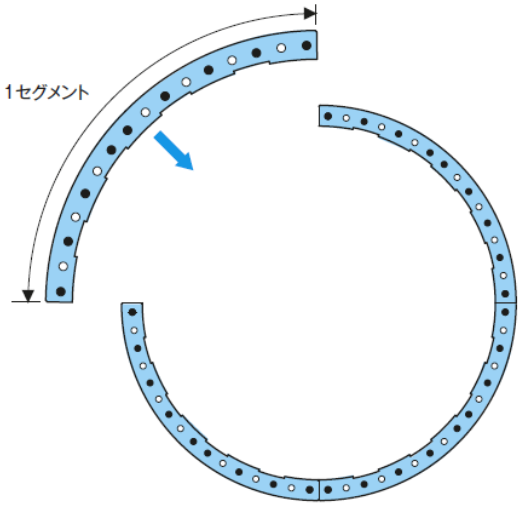
ピンホイール・ピンラックの分割
ピンホイール・ピンラックの分割については下記をご参照の上、手配時には納品図などで必ずご確認ください。
| 例1. | ピンホイールの例: | 例2. | ピンラックの例: | ||||
| PDU30-GW-190Pの場合8分割となります。 | PDU30-FR-200Pの場合、定尺ローラ数:26P 最小ローラ数:10P | ||||||
| 23/190P×2本 | ) | の組合せとなります。 | 26P×7本 | ) | の組合せとなります。 | ||
| 24/190P×6本 | 18P×1本 | ||||||
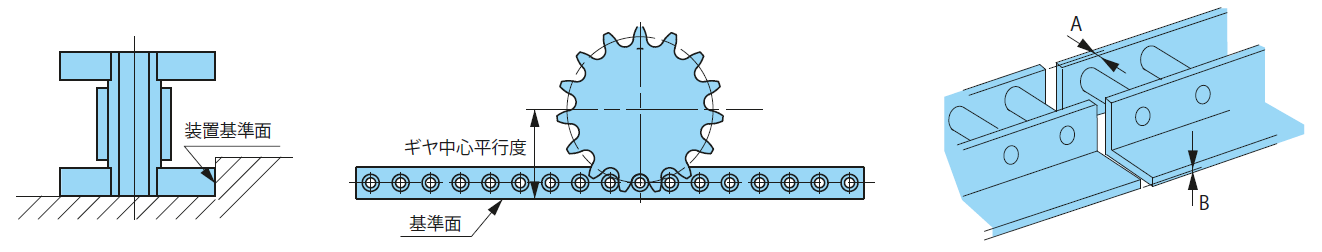
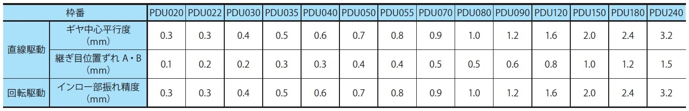
据え付け精度
| ピンホイール: | ピンホイールのフレーム凸部表面はローラ取付け穴と同芯加工してありますので芯出し基準面として装置のインロー部に嵌め込んで取り付ける事ができます。 装置インロー部の精度は下記表の「インロー部振れ精度」以内で仕上げてください。 |
| ピンラック: | ピンラックの装置側取付け基準面とピンギヤ中心の平行度は下表「ギヤ中心平行度」の値以下になるよう事前に装置間で平行度を出しておいてください。 ピンラック同士の継目における相互の位置ずれはA・Bは下表の値以下になるように取付けてください。 |
[クリックで拡大]
[クリックで拡大]
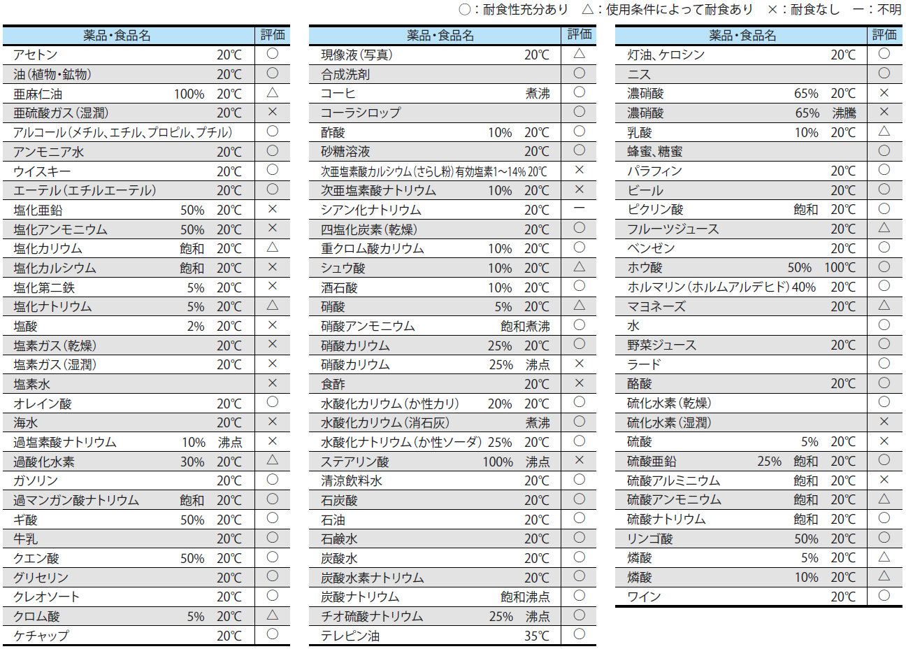
ステンレスタイプの耐食性に関する参考資料
耐食性は、使用条件によって相当変化しますので、下表は保証の程度を表したものではありません。下表を参考にして、実際の使用条件のもとで前もってテスト試料品などで耐食性を確認してください。
[クリックで拡大]
