技術資料 ケーブルベヤ - ケーブルベヤの使用限度
ケーブルベヤの寿命とは
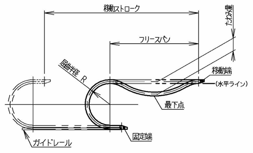
ケーブルベヤは稼動(往復移動)に伴い、リンク連結部のピンおよび穴の摩耗や、ノーバックベント規制部の摩滅などの影響により、フリースパン部のたわみが進行します(右図参照)。
その影響により、ケーブル・ホースの保護性およびケーブルベヤや本体の安定した挙動が確保できなくなった時点を寿命と判断します。
判断目安は下記1、2いずれかの小さい方に達した場合とします。
フリースパン部のたわみ量の限界値(目安)
1.フリースパン長さの10%分
2.ケーブルベヤの屈曲半径(R)分
(例)
フリースパン長さ:
500mm(⇒500mm×0%=50mm)→限界たわみ量(目安)50mm
ケーブルベヤ屈曲半径:R55
■ケーブルベヤが経年劣化などで、割れや欠けなど破損が発生した場合、そのケーブルベヤを寿命と判断します。
寿命の促進要因
ケーブルベヤは下記のような場合、短期間で寿命に至る場合があります。
- 1.高い加減速度と稼動頻度。
- 2.粉塵等の摩耗介在物の存在。
- 3.外部からの振動。
- 4.設置精度が悪い。
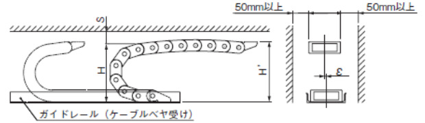
■ケーブルベヤ設置精度の目安(推奨)
- ・移動端、固定端位置の心ずれ(ε値)が許容値より小さいこと
- ・設置高さ(H'値)が推奨値内のこと〔注:総高さ(H値)で設置しないでください。〕
- ・余裕空間(S値)が推奨値よりも大きいこと
- ・ガイドレール(ケーブルベヤ受け)を設ける
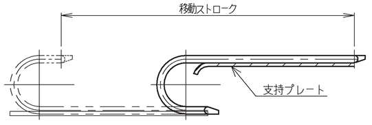
ケーブルベヤ延命策
ケーブルベヤのたわみを規制できるよう、稼動初期から支持ローラもしくは、支持プレートを設置しておくことでケーブルベヤ本体の延命が可能です。
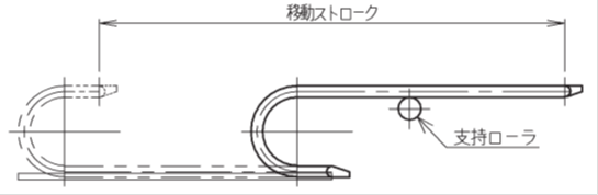
注)フリースパン部のたわみが進行した状態で、支持ローラや支持プレートを追加する場合には、その時点でのフリースパン部のたわみ量を考慮した設置位置(高さ)を、また、支持プレートの場合には形状(フリースパン部がレールに乗り移る部分)を設定する必要があります。
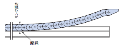
ロングスパン仕様寿命の目安
ロングスパン仕様では、使用に伴いリンク内周側が摩滅してきます。リンク高さの摩耗量(スライドシュ付の場合はスライドシュの摩耗量)が許容値(右表)に達する時点がお取替えの目安となります。TKP58H39・スライドシュ付、TKP68H46・スライドシュ付、TKP91(H56、H80)、TKC91(H56、H80)、TKMK 形、TKMT 形ではスライドシュのみの交換が可能です。スライドシュの延命効果については、ロングスパン仕様ページを参照ください。
| サイズ | 許容摩耗量 (mm) | |
|---|---|---|
| スライドシュなし | スライドシュ付 | |
| TKP35H22 | 1 | - |
| TKP45H25 | 1.5 | - |
| TKP58H39 | 1.5 | 5 |
| TKP62H34 | 1 | - |
| TKP68H46 | 1.5 | 5 |
| TKP90H50 | 1.5 | - |
| TKP125H74 | 1.5 | - |
| TKP91H56 | - | 7 |
| TKP91H80 | - | 7 |
| TKC34H25 | 1 | - |
| TKC47H36 | 1 | - |
| TKC64H50 | 1.5 | - |
| TKC85H68 | 1.5 | - |
| TKC91H56 | - | 7 |
| TKC91H80 | - | 7 |
| TKMK47H28/TKMT47H26 | - | 1.5 |
| TKMK65H42/TKMT65H38 | - | 1.5 |
| TKMK95H58/TKMT95H54 | - | 1.5 ※ |
| TKMK125H72/TKMT125H68 | - | 1.5 ※ |
※さらに大きい値(スライドシュの厚みが異なる)の仕様もあります。必要な場合は当社までお問合せください。
