技術資料 タイミングベルト・タイミングプーリ 選定
慣性負荷からの選定・選定例
選定に必要な項目
選定に必要な項目は次の通りです。それぞれの条件を定めてください。
- (1)回転運動体の場合
回転運動体の形状寸法、質量、回転速度、加(減)速時間、軸の直径、軸間距離1日の使用時間、起動頻度、速比、アイドラ使用の有無、その他の条件 - (2)直線運動体の場合
プーリピッチ円直径、直線運動体の質量、支持方法、支持機構の摩擦係数、運動速度、加(減)速時間、軸の直径、軸間距離、1日の使用時間、起動頻度、速比、アイドラ使用の有無、その他の条件
慣性モーメントの計算
慣性モーメントを次の式により求めます。
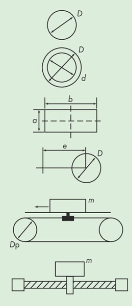
- (1) 回転運動体の場合
・中実円筒
I = 1 8 mD2・中空円筒
I = 1 8 m(D2 + d2)・矩形断面
I = 1 12 m(a2 + b2)・偏心回転体
I = 1 8 mD2 + me2 - (2) 直線運動体の場合
I = 1 4 mDp2
- (3) ボールネジ駆動の場合
I = 1 4 m L π 2
- (4) 総慣性モーメント
∑I = (I1 + I2 + ....)R2
※ベルトにより駆動される全運動体(従動プーリも含む)の慣性モーメントを左式にて合計します。
- I:各運動体の慣性モーメント kg・m2
- ∑I:総慣性モーメント
- m:回転体または直線運動体の質量 kg
- D:回転体の外径 m
- d:回転体の中空部内径 m
- a:矩形断面の辺の長さ m
- b:矩形断面の辺の長さ m
- e:偏心距離 m
- Dp:プーリピッチ円直径 m
- L:ネジのリード m
- R:減速比(駆動プーリ歯数/従動プーリ歯数)
加(減)速トルクの計算
加(減)速トルクを次の式により求めます。
Pa = ∑I × (n2 - n1) 9.55 × ta
- Pa:加(減)速トルク N・m
- n1:加(減)速前の回転速度 r/min
- n2:加(減)速後の回転速度 r/min
- ta:加(減)速時間 s
連続負荷トルクの計算
連続負荷トルクを次の式により求めます。
(1) 水平移動の場合
Pc = 4.9 × mµDp
(2) 垂直移動の場合
Pc = 4.9 × mDp
- Pc:連続負荷トルク N・m
- µ:運動体支持機構の摩擦係数
設計トルクの決定
設計トルクは次の式により求めます。Ko、Kaは下記枠内の数値を使用します。
Pt = (Pa + Pc) × (Ko +Ki + Ks) × Ka × Ke※
負荷補正係数
| 1日の運転時間 h | <3 | 3~10 | 10< |
|---|---|---|---|
| Ko | 1.2 | 1.3 | 1.5 |
起動停止頻度補正係数
| 1日の起動停止回数 | ≦10 | 11~100 | 101~999 | 1000≦ |
|---|---|---|---|---|
| Ka | 1.1 | 1.2 | 1.3 | 1.5 |
- Pt:設計トルク N・m
- Pa:加(減)速トルク N・m
- Pc:連続負荷トルク N・m
- Ko:負荷補正係数 左表
- Ki:アイドラ使用時の補正係数...表2
- Ks:増速時の補正係数...表3
- Ka:起動停止頻度補正係数 左表
- Ke:使用雰囲気係数 1.2
※ウルトラPXベルトHA仕様(耐油/耐水仕様)を油や水が掛かる雰囲気で使用する際、PXベルト耐水仕様を水の掛かる雰囲気で使用する際は、使用雰囲気係数(Ke)として1.2を乗じてください。
※これ以降は「ベルトサイズ・プーリ歯数の決定」より続けて選定を進めてください。
選定計算例(慣性負荷からの選定)
選定に必要な項目
選定に必要な項目は次の通りとします。
| 項目 | 内容 |
|---|---|
| (工作機械のテーブル駆動) | |
| プーリピッチ円直径 | 50mm以下 |
| 直線運動体の質量 | 50kg |
| 支持方法、支持機構の摩擦係数 | LMガイド、摩擦係数 μ=0.1 |
| 運動速度 | 1000r/min |
| 加(減)速時間 | 0.3s |
| 軸の直径 | 20mm |
| 軸間距離 | 1400mm |
| 1日の使用時間、起動頻度 | 12時間/日、1000回/日 |
| 速比 | 1:1 |
| アイドラ使用の有無 | なし |
| その他の条件 | なし |
慣性モーメントの計算
まず、慣性モーメントを求めます。この場合直線運動体なので次の式が該当します。また条件よりプーリは30P5M(歯数30、Dp=47.75mm)を仮に選定します。
I = 1 4 mDp2 = 1 4 × 50 × 0.047752 = 0.0285kg・m2
加(減)速トルク、連続負荷トルクの計算
加(減)速トルクと連続負荷トルクをそれぞれ求めます。
加(減)速トルク Pa = I × (n2 - n1) 9.55 × ta = 0.0285 × (1000 - 0) 9.55 × 0.3 = 9.95N・m
連続負荷トルク Pc = 4.9 × mµDp = 4.9 × 50 × 0.1 × 0.04775 = 1.17N・m
設計トルクの決定
加(減)速トルクと連続負荷トルクの合計に各補正係数を乗じて設計トルクを求めます。
Pt = (Pa + Pc) × (Ko + Ki + Ks) × Ka = (9.95 + 1.17) × (1.5 + 0 + 0) × 1.5 = 25.02N・m
設計トルクの決定後は、一般選定(トルクからの選定)にしたがってください。
ベルトサイズ・プーリ歯数の決定
ベルト長さと軸間距離の決定
- (1) ベルトの概算長さ(L')を計算します。
L' = 2C + 1.57 (Dp + dp) + (Dp - dp)2 4C = 2 × 1400 + 1.57 (47.75 + 47.75) + (47.75 - 47.75)2 4 × 1400 = 2950mm
この概算長さに最も近いベルトは品種・寸法一覧より3050UP5M(610歯)となります。
- (2) このときの軸間距離(C)を計算します。
B = L - 1.57 (Dp + dp) = 3050 - 1.57 (47.75 + 47.75) = 2900
C = B + B2 - 2(Dp - dp)2 4 = 2900 + 29002 - 2(47.75 - 47.75)2 4 = 1450mm
かみ合い歯数による補正
小プーリにかみ合うベルトの歯数を求め、かみ合い補正係数を決定します。
この場合速比が1:1なのでかみ合い歯数は30歯の1/2の15歯、よってかみ合い補正係数は1.0です。
ベルト幅の決定
設計トルクを満足するベルト幅を最終的に決定します。
Kw ≧ Pt Pr × Km × KL = 25.02 9.37 × 1.0 × 1.2 = 2.23
よって幅係数を満足するベルトはUP5M25(ベルト幅25mm)となります。
選定結果
- ベルト:BG3050UP5M25-HC
- プーリ:PT30P5M25AFまたはBF
- 軸間距離:1450mm
