技術資料 ドライブスプロケット ご使用になる前に
構造・材質・歯先仕様・軸穴仕様
1. 構造
RSスプロケットはJISで規定されている4種類の構造があります。
| 形式記号 | A形 (平板形) |
B形 (片ハブ形) |
C形 (両ハブ形) |
SD形 (シングルデュアル) |
|---|---|---|---|---|
| 構造 |

|

|

|

|
| 強力チェーン(SUPER-H・HT等)多列 注1 | 単列チェーンを2本同時に掛けられる形状 | |||
| HB形 | HC形 | |||
| 構造による使い分け | トルクリミタのセンタメンバ等、回転体に取付ける場合などに使用します。 | もっとも汎用的に使用できます。 | 従動用の大スプロケットやB形ではキー面圧が不足する場合などに使用します。 | 単列チェーンを2本同時に掛けて使用します。 |
注記
1.強力チェーン多列(HB形、HC形)は総歯幅(横ピッチ)が標準と異なります。
2. 材質
RSスプロケットは下記の材質を標準化しています。
| 鋼種 | 材質 |
|---|---|
| 炭素鋼 | *機械構造用炭素鋼 |
| 圧延鋼 | *一般構造用圧延鋼 |
| ステンレス鋼 | *オーステナイトステンレス鋼 |
| 樹脂 | *エンジニアリングプラスチック(エンプラ) |
| 焼結合金 | *鉄系焼結合金(RS25スプロケットの一部に使用) |
3. 歯先仕様
| 仕様 | |
|---|---|
| 歯先硬化仕様 | 歯部の強度と耐摩耗寿命向上を必要とする場合、歯先硬化スプロケットを使用します。 TOUGH TOOTHは全ての歯先に硬化処理をしています。 |
| 歯先生(なま)仕様 | 歯先部の硬化はしていません。 RSスプロケットの大歯数範囲では歯先部は生仕様です。 |
4. 軸穴仕様
スプロケットを相手軸に取付ける際の軸穴仕様は下記の3種類があります。
| シリーズ | 外観 | 仕様 |
|---|---|---|
| 標準下穴 |

|
|
| フィットボア® |


|
|
| ロックスプロケット |

|
|
5. ローラチェーン・スプロケットの取扱
5.1 歯先硬化
次のような使用条件では、スプロケットの歯先を硬化する必要があります。
- 1. 歯数が24枚以内の小歯数で、伝動能力表記載の最高回転速度の1/8以上の場合。
- 2. 速比が4:1より大きい場合の小スプロケット。
- 3. 低速大荷重の場合。
- 4. 歯を摩耗させる雰囲気の場合。
5.2 歯数
高速軸側スプロケットの歯数を、できるだけ大きくする程、円滑な伝動になります。
一般に歯数は15歯以上が適当です。しかし速比が大きく、低速側スプロケットの歯数が120歯をこえると、チェーンのわずかな摩耗伸びにより噛み合い不良を生じることがあります。
そのため高速側スプロケットの歯数を少なくなるように設計ください。その場合でも13歯以上の歯数をおすすめします。
なお、ごく低速で衝撃がかからない場合には、12歯以下の歯数のスプロケットも使用できます。
5.3 追加工の注意
1. 軸穴加工
- ・最大軸穴加工寸法
最大軸穴仕上げ加工寸法は各寸法表に記載している最大軸穴径以下となります。
なお、JIS規格キー以外をご使用される場合は当社へ加工内容をご指示ください。 - ・加工基準
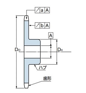
歯形部の外径Doまたはハブ外径DHを基準に加工ください。
このとき、歯底部の振れaおよび歯部端面の横振れbは下表の値以下になるようにご確認ください。
| 歯底円直径(df) | 90以下 | 90をこえ 190以下 |
190をこえ 850以下 |
850をこえ 1180以下 |
1180を こえるもの |
|---|---|---|---|---|---|
| 歯底の振れ a | 0.15 | 0.0008df+0.08 | 0.76 | ||
| 横振れ b | 0.25 | 0.0009df+0.08 | 1.14 | ||
2. A形スプロケットの溶接
A形スプロケットにハブを溶接し使用する事は溶接による歪み、歯部端面の振れの原因になり品質を維持できなくなる場合がありますので避けてください。
また、A形歯先硬化仕様のスプロケットは溶接により硬度低下の恐れがありますので同様に溶接を避けてください。
3. ハブ外径の加工
ハブ外径の追加工は行わないでください。もし加工を行われる場合は当社にお問合せください。
5.4 スプロケットの表面処理
標準スプロケットにめっき、黒染め、その他の表面処理をされる場合は下記厳守ください。
- ・防錆油・防錆塗料が塗布されていますので、完全に取り除きます。
- ・歯先硬化スプロケットに電解めっきなど、水素脆性破壊の恐れがある処理を施される場合は、防止処理を十分に行います。
新JISキー
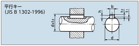
| 軸穴径 d |
キー呼称の寸法 幅 × 高さ b×h |
キー溝の深さ | |
|---|---|---|---|
| 軸 t1 | ボス d + t2 | ||
| 6をこえ 8以下 | 2×2 | 1.2 | d + 1.0 |
| 8 〃 10 〃 | 3×3 | 1.8 | d + 1.4 |
| 10 〃 12 〃 | 4×4 | 2.5 | d + 1.8 |
| 12 〃 17 〃 | 5×5 | 3.0 | d + 2.3 |
| 17 〃 22 〃 | 6×6 | 3.5 | d + 2.8 |
| 20 〃 25 〃 | (7×7) | 4.0 | d + 2.3 |
| 22 〃 30 〃 | 8×7 | 4.0 | d + 3.3 |
| 30 〃 38 〃 | 10×8 | 5.0 | d + 3.3 |
| 38 〃 44 〃 | 12×8 | 5.0 | d + 3.3 |
| 44 〃 50 〃 | 14×9 | 5.5 | d + 3.8 |
| 50 〃 55 〃 | (15×10) | 5.0 | d + 5.3 |
| 50 〃 58 〃 | 16×10 | 6.0 | d + 4.3 |
| 58 〃 65 〃 | 18×11 | 7.0 | d + 4.4 |
| 65 〃 75 〃 | 20×12 | 7.5 | d + 4.9 |
| 75 〃 85 〃 | 22×14 | 9.0 | d + 5.4 |
| 80 〃 90 〃 | (24×16) | 8.0 | d + 8.4 |
| 85 〃 95 〃 | 25×14 | 9.0 | d + 5.4 |
| 95 〃 110 〃 | 28×16 | 10.0 | d + 6.4 |
| 110 〃 130 〃 | 32×18 | 11.0 | d + 7.4 |
| 125 〃 140 〃 | (35×22) | 11.0 | d + 11.4 |
| 130 〃 150 〃 | 36×20 | 12.0 | d + 8.4 |
| 140 〃 160 〃 | (38×24) | 12.0 | d + 12.4 |
| 150 〃 170 〃 | 40×22 | 13.0 | d + 9.4 |
| 160 〃 180 〃 | (42×26) | 13.0 | d + 13.4 |
| 170 〃 200 〃 | 45×25 | 15.0 | d + 10.4 |
| 200 〃 230 〃 | 50×28 | 17.0 | d + 11.4 |
| 230 〃 260 〃 | 56×32 | 20.0 | d + 12.4 |
| 260 〃 290 〃 | 63×32 | 20.0 | d + 12.4 |
| 290 〃 330 〃 | 70×36 | 22.0 | d + 14.4 |
| 330 〃 380 〃 | 80×40 | 25.0 | d + 15.4 |
| 380 〃 440 〃 | 90×45 | 28.0 | d + 17.4 |
| 440 〃 500 〃 | 100×50 | 31.0 | d + 19.5 |
旧JISキー
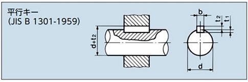
| 軸穴径 d |
キー呼称の寸法 幅 × 高さ b×(t2+t1) |
キー溝の深さ | |
|---|---|---|---|
| 軸 t1 | ボス d + t2 | ||
| 10以上 13以下 | 4×4 | 2.5 | d + 1.5 |
| 13をこえ 20 〃 | 5×5 | 3.0 | d + 2.0 |
| 20 〃 30 〃 | 7×7 | 4.0 | d + 3.0 |
| 30 〃 40 〃 | 10×8 | 4.5 | d + 3.5 |
| 40 〃 50 〃 | 12×8 | 4.5 | d + 3.5 |
| 50 〃 60 〃 | 15×10 | 5 | d + 5 |
| 60 〃 70 〃 | 18×12 | 6 | d + 6 |
| 70 〃 80 〃 | 20×13 | 7 | d + 6 |
| 80 〃 95 〃 | 24×16 | 8 | d + 8 |
| 95 〃 110 〃 | 28×18 | 9 | d + 9 |
| 110 〃 125 〃 | 32×20 | 10 | d + 10 |
| 125 〃 140 〃 | 35×22 | 11 | d + 11 |
| 140 〃 160 〃 | 38×24 | 12 | d + 12 |
| 160 〃 180 〃 | 42×26 | 13 | d + 13 |
| 180 〃 200 〃 | 45×28 | 14 | d + 14 |
| 200 〃 224 〃 | 50×31.5 | 16 | d + 15.5 |
| 224 〃 250 〃 | 56×35.5 | 18 | d + 17.5 |
