技術資料 直動機器 リニスピードジャッキ 選定
必要条件
使用機械 ..... テーブルリフタ、圧入機etc
レイアウト.....
ジャッキ2台同期(モータ別駆動もしくは1台のモータでカップリング連結)など
- 最大荷重(W) .....負荷またはワークの重量 N
- ネジ軸速度(V) .....ジャッキの必要速度 m/min
- ストローク .....実際に使用するストローク mm
取付形状 .....フェイスマウント、フランジ固定など
据付状態 .....ベース固定、軸端クレビスなど
タイムサイクル
選定手順
1. 補正荷重Wsの算出
負荷の性質を考慮し、使用係数(表1)を参照の上、補正荷重Wsを求めます。
補正荷重 Ws (kN) = 最大荷重 W (kN)×使用係数 Sf
表1 使用係数 Sf
| 負荷の性質 | 使用例 | 使用係数 |
|---|---|---|
| 衝撃の無い円滑な作動 負荷慣性 小 |
バルブの開閉 コンベヤ切換装置 |
1.0~1.3 |
| 軽い衝撃のある作動 負荷慣性 中 |
各種移動装置 各種リフタ昇降 |
1.3~1.5 |
| 大きな衝撃、振動のある作動 負荷慣性 大 |
台車による物搬送、圧延ローラの位置決め保持 | 1.5~3.0 |
注)上記使用係数は一般的な目安であり、使用条件を考慮して決定ください。
2. ジャッキ1台当たりの荷重Wの算出
補正荷重Wsよりジャッキ1台当たりの荷重Wを求めます。連動運転の場合は連動係数(表2)を参照の上計算します。
ジャッキ1台当たりの荷重 W (kN) = 補正荷重 Ws (kN) ジャッキ使用台数×連動係数 fd
表2 連動係数 fd
| 連動台数(台) | 2 | 3 | 4 | 5~8 |
|---|---|---|---|---|
| 連動係数 | 0.95 | 0.9 | 0.85 | 0.8 |
3. リニスピードジャッキの形番を仮選定
ジャッキ1台当たりの荷重Wを満足する許容推力を持つ形番を仮選定します。
ストロークは使用ストロークに余裕を見込んで選定します。取付形式、軸配置より形番を選定します。
注意事項
- (1)使用荷重(静的・動的)・衝撃荷重とともにに許容推力を超えないように、安全を見込んだ十分な形番をお選びください。
- (2)ジャッキのストローク以上で使用しますとジャッキが破損するおそれがあります。リニスピードジャッキは抜け止めを設けていますが、据付時の手動操作中にネジが抜け落ちないためのものです。
- (3)いかなる場合も当て止めを行わないでください。当て止めを行いますとジャッキ内部に重大な損傷をおこします。
- (4)フランジマウントの場合は、許容推力50%以下に制限が必要な荷重方向があります。詳細(こちら)をご参照ください。
6. 入力軸許容オーバハングロードの検討
入力軸にベルトなどを取付ける場合は、許容オーバハングロード以下になっているかを確認します。
許容値を超えている場合はジャッキの枠番を上げて再検討します。
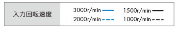
7. 必要入力回転速度の確認
必要ネジ軸速度よりジャッキの必要入力回転速度を求めます。
N = V ℓ ×R
N:入力回転速度 r/min
V:ネジ軸速度 m/min
ℓ:ネジリード m
R:ウォーム速比
仕様の各項目は製品ページをご参照ください。
許容入力回転速度は3000r/minです。
この回転速度以下になることをご確認ください。
8. 負荷時間率の確認
1サイクルあたりの運転時間の割合を確認します。
負荷時間率%EDが許容値以内であるか確認します。
詳細はこちらをご参照ください。
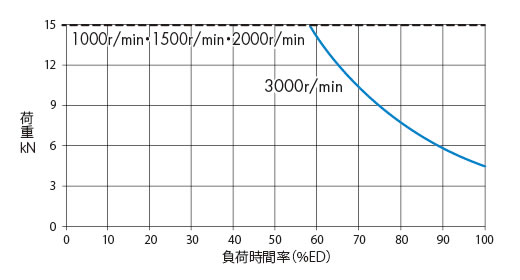
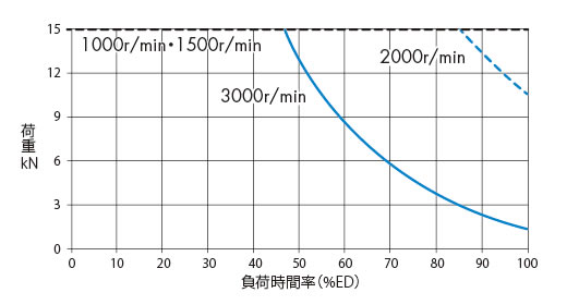
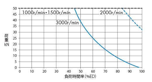
リニスピードジャッキは周囲温度を含んだ減速部表面温度90℃以下でご使用ください。
下表は減速部表面温度90℃以下となる負荷率(%ED)の目安を示します。 (保証値ではありません。)
実際のご使用に当たっては減速部表面温度をご確認ください。
SJ015H
周囲温度 20℃
[クリックで拡大]
周囲温度 30℃
[クリックで拡大]
周囲温度 40℃
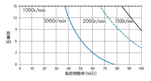
[クリックで拡大]
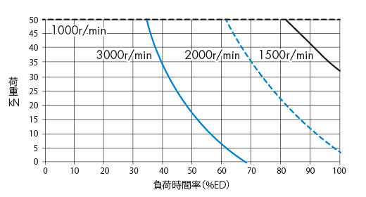
SJ030H
周囲温度 20℃
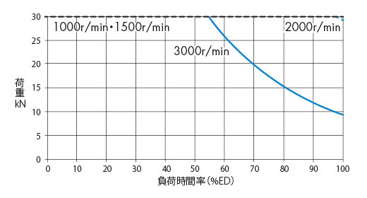
[クリックで拡大]
周囲温度 30℃
[クリックで拡大]
周囲温度 40℃
[クリックで拡大]
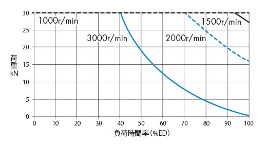
SJ050H
周囲温度 20℃
[クリックで拡大]
周囲温度 30℃
[クリックで拡大]
周囲温度 40℃
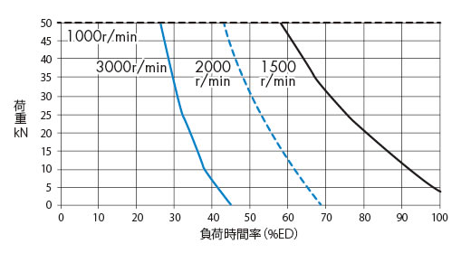
[クリックで拡大]
%ED = 1サイクルの運転時間 1サイクルの運転時間 + 1サイクルの休止時間 ×100(%)
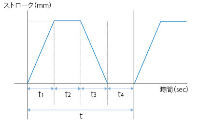
タイムサイクル表より負荷時間率%EDを求める式は下記の通りです。
%ED = t1 + t3 t1 + t2 + t3 + t4 ×100(%)
9. 必要入力トルクの確認
必要入力トルクを計算します。
サーボモータをご使用の場合は、サーボモータの許容トルクを満足する形番を選定ください。
T = W×ℓ 2×π×R×η + To
T:必要入力トルク N・m
W:昇降荷重 N
ℓ:ネジリード m
π:円周率 3.14
R:ウォーム速比
η:ジャッキ総合効率または起動効率 注)
To:無負荷空転トルク N・m
※ネジリード、ウォーム速比、総合効率、無負荷空転トルクは各製品の主要諸元ページをご参照ください。ネジリードの単位にご注意ください。
例) 25mm ---> 0.025m
注)必ず起動効率にて起動時の必要入力トルクを確認願います。
10. 必要入力容量の確認
P = T×N 9550
T:必要入力トルク N・m
P:必要入力容量 kW
N:入力回転速度 r/min
11. 入力軸ねじりトルクの確認
同一線上に接続することができるジャッキの連動台数には、軸強度による制限がありますので、許容入力軸トルクをご参照ください。
例)ジャッキの配置が下図のようにストレート形の場合、駆動源のジャッキには2台分の必要入力トルクが入力軸に伝達されます。
この2台分のトルクが許容入力軸トルク以下であるか確認します。
※起動時のピークトルクが許容入力軸トルクを超えないようにご注意ください。
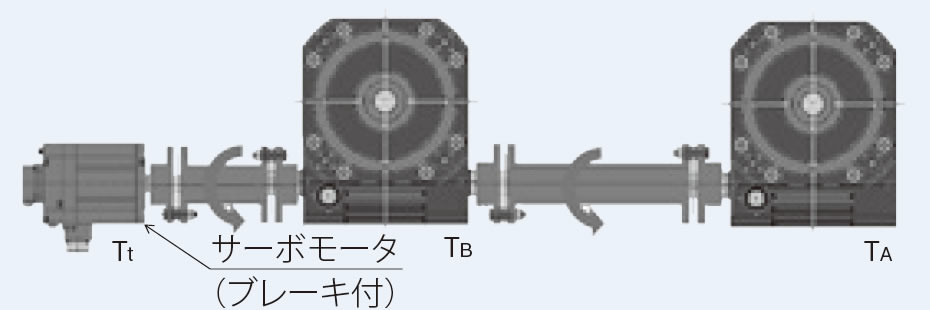
ジャッキAのみの必要トルクTA
ジャッキBのみの必要トルクTB
駆動源必要トルクTt = TA + TB < 許容入力軸トルク
許容入力軸トルクは各製品の主要諸元ページをご参照ください。
12. オプションの決定
使用条件に合わせてオプションを選定します。
- ・出力オプション
- ・制御オプション
13. リニスピードジャッキ本体形番の決定
リニスピードジャッキ本体の正式形番を決定します。
選定例
必要条件
使用機械 ..... 4台連動押上げリフタ、工場内常温(30℃)、粉塵無し
レイアウト .....2台のジャッキを連結し、1台のブレーキ付サーボモータで駆動。これを2組で昇降する。(図1)
運転サイクル .....図2参照
- ・最大荷重(W):28kN/4
- ・ネジ軸速度(V):180mm/s(10.8m/min)
- ・ストローク:540mm
取付形状 .....フランジマウント、フランジはケース側
据付状態 .....ベース固定-軸端固定(テーブル形先端金具取付)
期待寿命 .....30サイクル×2回/時間×8時間/日×250日/年×3年間使用
図1 レイアウト
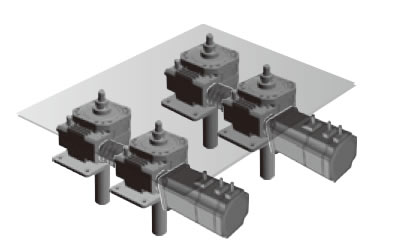
2台のジャッキ(計4台)で昇降
図2 タイムサイクル
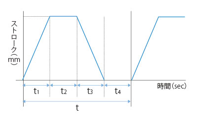
| 1サイクル当りの各時間 | |
|---|---|
| t1 | 3sec |
| t2 | 2sec |
| t3 | 3sec |
| t4 | 6sec |
| t | 14sec |
-
1. 最大荷重より補正荷重Wsは(使用係数sf = 1.3とする。)
Ws = 28×1.3 = 36.4kN
-
2. ジャッキ1台当たりの荷重Wは(連動係数fd = 0.85とする。)
W = 36.4 / 4 / 0.85 = 10.7kN
-
3. ジャッキ1台当りの荷重より形式SJ015Hを仮選定します。
使用ストローク540mmよりジャッキのストロークは余裕を見込み600mmとします。
-
4. 使用頻度より期待走行距離を求めます。
期待走行距離 = 0.54×2×30×2×8×250×10-3×3 = 388.8km
ネジ軸の期待寿命はこちら参照の上、期待走行距離と荷重の交点よりジャッキの枠番を求めます。
SJ015Hでは期待走行距離を満足できないので、形式はSJ030Hとなる。...OK
-
5. 圧縮荷重がかかりますので、こちらの座屈計算式にて許容座屈荷重の検討を行います。安全率sf = 4とします。
Pcr = 20×104(30.72/775)2 = 295.8kN
sf = 295.8/10.7 > 4 ...OK
6. 入力軸オーバハングロードの検討はブレーキ付サーボモータ直結駆動のため不要とします。
-
7. 必要ネジ軸速度よりジャッキの必要入力回転速度を求めます。
N = 10.8 / 0.025×6 = 2592 r/min
ネジ軸速度、ネジリードの単位にご注意ください。
(180mm/s --->10.8m/min、25mm --->0.025m) -
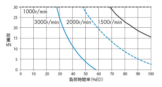
8. タイムサイクル表より負荷時間率を確認します。
%ED = (3 + 3) / 14×100 = 43%ED
許容負荷時間率はこちらより確認します。
入力回転速度2592r/min、周囲温度30℃より、許容負荷時間率は50%EDとなります。
50%ED > 43%ED ...OK
×(ドラッグで移動できます)リニスピードジャッキは周囲温度を含んだ減速部表面温度90℃以下でご使用ください。
下表は減速部表面温度90℃以下となる負荷率(%ED)の目安を示します。 (保証値ではありません。)
実際のご使用に当たっては減速部表面温度をご確認ください。
SJ015H
周囲温度 20℃
[クリックで拡大]
周囲温度 30℃
[クリックで拡大]
周囲温度 40℃
[クリックで拡大]
-
9. ジャッキ1台当りの必要入力軸トルクを計算します。
定常時の必要入力軸トルク
T = 10.7×1000×0.025 / 2 / π / 6 / 0.87 + 6 = 14.2N・m
ネジリード、速比、総合効率、無負荷空転トルクは各製品の主要各製品の主要諸元ページにてご確認ください。
総合効率は入力回転速度毎の値をご使用ください。ネジリードの単位にご注意ください。(25mm --->0.025m)
起動時の必要入力軸トルク
T' = 10.7×1000×0.025 / 2 / π / 6 / 0.65 + 6 = 16.9N・m
起動効率は各製品の主要諸元ページにてご確認ください。
-
10. 1台のサーボモータで2台のジャッキを駆動するため、ブレーキ付サーボモータ1台当りの必要入力軸トルクを計算します。
サーボモータに必要なトルクは
Tm = 14.2×2 = 28.4N・m
また、サーボモータに必要な起動トルクは
T'm = 16.9×2 = 33.8N・m
サーボモータの選定では、定格回転速度3000r/minで定格トルクが28.4N・mを満足するブレーキ付仕様をご検討ください。
また、起動トルクが満足することもご確認ください。参考)サーボモータの必要容量
P = 28.4×3000 / 9550 ≒ 9kW
-
11. 2台のジャッキが同一線上に連結されているので、駆動側に近いジャッキの入力軸にはジャッキ2台分のトルクが掛かります。
ジャッキの入力軸トルクがSJ030H記載の許容入力軸トルク以下であるか確認します。ジャッキ2台分のトルク = 16.9 + 16.9 < 65N・m ...OK
-
12. ジャッキのオプションは
軸端形状(先端金具) --->テーブル形先端金具付
粉塵が少ない --->必要に応じジャバラ(特形品)を使用ください
-
13. 以上の検討よりリニスピードジャッキ形番はSJ030H-TCT6Mが決定されます。
