技術資料 直動機器 リニスピードジャッキ 許容座屈荷重
許容座屈荷重表
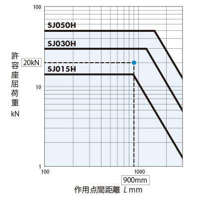
- ・圧縮荷重で使用する場合は、このグラフより座屈荷重に対するジャッキ枠番を決定してください。座屈選定グラフは座屈安全率SF=4を見込んだグラフです。
- (1)下図据付状態から作用点間距離Lを選択してください。 (下図の据付状態以外は別途お問合せください。)
- (2)ジャッキ1台あたりの荷重W(縦軸)と作用点間距離(横軸)の交点からジャッキの枠番をお選びください。
- ・横荷重は掛からないようにしてください。右図の座屈選定グラフには横荷重は考慮していません。
- ・据付状態としてはネジ軸が引張荷重となる構造に装置を工夫してくだされば、座屈が無く経済的です。
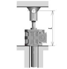
ベース固定-軸端 支持
ベース固定-軸端 固定

- 注)
- 1.このグラフの----線は荷重W=20kNのとき、上記の据付状態の時で作用点間距離900mmの例を示しています。
このグラフは座屈安全率sf=4を見込まれており、今回の場合では縦軸・横軸の交点を満足するジャッキSJ030Hが選定できます。 - 2.詳細な検討が必要な場合は、下記の計算式にてご確認ください。
作用点間距離:L(据付面~負荷取付面までの距離)
| SJ015H | SJ030H | SJ050H | |
|---|---|---|---|
| テーブル形先端金具(M) | 25mm | 33mm | 33mm |
| I形先端金具(I) | 50mm | 75mm | 80mm |
| X寸法(MIN) | 187mm | 202mm | 236mm |
テーブル形またはI形先端金具をご使用される場合、実ストロークに先端形状毎の長さを合計してください。
例) SJ030H ストローク500mmでI形先端金具を使用する場合。
500 + 277 = 777mm
注)
お客様がご用意される先端金具を取付ける場合は実ストロークにX寸法(MIN)と先端金具の長さを合計してください。なお、X寸法にはネジ軸端の先端金具取付用ネジ長さ32mmは含んでおりません。

許容座屈荷重計算式
ジャッキのネジ軸が許容できる座屈荷重は下記により計算できます。
PCR = m×
d2
L
2
PCR > W×Sf となるようにしてください。
PCR:許容座屈荷重 N
d:ネジ谷底径 mm
m:支持係数(20×104)
L:作用点間距離 注) mm
W:ジャッキ1台当たりの荷重 N
Sf:座屈安全率(一般的には4)
ベース固定-軸端 支持
ベース固定-軸端 固定
| 許容座屈計算例 |
|---|
|
SJ030H-TUT8M(ストローク800mm)を荷重(W)24500N、 PCR = 20×104×(30.72/1035)2 *L = 1002 + 33 = 1035mm ST800mmのX寸法:1002mm テーブル先端金具:33mm 製品ページより |
横荷重について
リニスピードジャッキは軸方向以外の荷重には耐えられません。
横荷重が掛かる場合は、右図のようにガイドを設けてジャッキには直接横荷重等が働かないようにご配慮ください。

