Technical Data  Linear actuator  Power Cylinder  Handling

Installation / maintenance :G Series

Mounting

Mounting Direction

Any of horizontal, vertical and inclined direction is allowed.

Installation environment

  • ・All models are totally enclosed structures so that they can be used normally outdoors, however, under adverse conditions exposed to constant water and steam etc., and snow accumulation, although they are an outdoors type, an appropriate cover is required. The power cylinder can generally be used in a range of -15℃ to 40℃, although it varies depending on the use conditions. When using at 40℃ or higher, always protect with a heat insulating cover, etc. Never use in flammable environments. There is a risk of explosions and fire hazards. Do not use in areas subject to vibration or shock of 1 G or more.
  • ・For use in a misty atmosphere, consult with us.
  • ・When using a cylinder of the cabtire cable lead wire specification outdoors, carry out waterproofing treatment sufficiently.

Mounting

  • ・For installation of the main body, use a trunnion mount or clevis mount (parallel only). Install the tip with a U-shaped or an I-shaped end fitting.
  • ・Apply grease to the trunnion pin and the trunnion hole for trunnion mounting. Also, apply grease to the connecting pin of the end fitting and the connecting pin for clevis mounting. Mounting

    Trunnion mount

    Clevis mount

  • ・When the main body greatly swings by operation of the cylinder, consider using a sliding bearing or a rolling bearing for the connecting part. Cylinders whose trunnion hole is provided with sliding bearing are available upon request.
  • ・When the trunnion pin or connecting pin for the clevis or the end fitting is directed in the vertical direction (when the cylinder is installed horizontally), and the main body swings, take countermeasures for wear such as inserting a bearing member into the trunnion hole, the clevis fitting, or the side part of the end fitting.

Manual operation

When manually adjusting the stroke, rotate the manual shaft on the motor opposite load side with the manual handle after releasing the brake. For how to release the brake, refer to the Operation Manual. The manual handle is attached to the standard product.

Warning

When load is applied to the rod, remove the load before releasing the brake.

For the rod stroke per one turn of the manual shaft, refer to the standard model list (click here).

Prevention of rod rotation

  • 1.Prevention of rod rotation is required as the rod generates the rotational force (click here) along with the thrust. The rod rotational force at rated thrust is shown in the standard model list.
  • Generally, rotation can be mostly prevented by installing the rod end to a driven machine.
  • 2.When operating with the end set free or in the case of application to install pulleys to pull a rope, a rod anti-rotation is normally required. Use a rod anti-rotation specification (option symbol M) for the power cylinders.

Lateral load on rod

When the radial load work on the cylinder or unbalanced load on the rod, take the following countermeasures.

(1)Side load …Install guide roller etc., on the rod part. (Fig. 2)

Fig. 2 Side load

Side load

Install a guide roller and avoid directly a lateral load on rods.

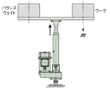
(2)Unbalanced load …Install balance weight etc. (Fig. 3)

Fig. 3 Unbalanced load

There is when an unbalanced load, install a counter weight etc.

※A guide is required in this layout.

Unbalanced load

Megger testing

Megger testing is prohibited for this cylinder. It may break the built-in power module. Remove the brake wiring for the terminal block when conducting megger testing of the external circuits.

Setting of stroke adjusting external LS

  • ・A type of option which allows the limit switch to be mounted on the power cylinder body, which can be selected.
  • ・Regulate the both ends of the stroke by the limit switch.
  • ・Use within the stroke range. If the stroke is exceeded, breakage may occur.
  • ・Take a coasting amount (click here) into consideration for adjustment of the limit switch.
  • ・When using the cylinder at the nominal stroke 100%, set the limit switch so that the cylinder stops within the XA dimension in the Dimensions Table.
  • ・When using a slow stop (25 mm/s or less) with an inverter, etc., the external LS may not be able to be set near the MIN position of the XA dimension of the nominal stroke. If you intend to use it in such a way, please contact us.
  • ・When synchronized operating two or more power cylinders, install a limit switch at the extend limit and retract limit on each cylinder to stop each cylinder. Avoid using a single limit switch to control all of cylinders, as this will result in a cumulative error in stroke.
  • ・As a high-speed type (U, H speed) of the power cylinder G series has a long coasting distance, the striker may override the limit switch.
    (The striker for the U-speed power cylinder overrides the limit switch at the rated lifted load. ) For this reason, make sure to allow a limit signal to be self-held on the control circuit.
  • ・Adjustment of the limit switch for thrust detection of the C type must not be carried out by the customer. The preset value of thrust detection may change greatly.

Maintenance

Greasing on screw

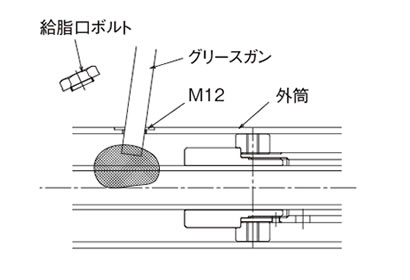
Use the screw as it is because it has been applied with greased in advance. Refill grease with reference to Table 1 and 2 as a guide. To apply grease to the screw, remove the greasing port bolt on the outer cylinder and advance the rod in the full stroke and apply grease to the outer circumference of the screw with a grease gun, and then reciprocate the rod within the stroke to be used. Repeat this operation a few times.

Greasing on screw

Amount of grease per stroke 100mm is approx. 10 to 15g.

Warning

Never insert your finger into the grease port.
If the cylinder operates with your finger inserted, your finger may be injured.

Table 1 Recommended grease (Be sure to use EP (extreme pressure) grease. )

Use classification Company name Grease name
Screw shaft TSUBAKIMOTO CHAIN CO. JWGS100G
Idemitsu ※DAPHNE EPONEX SR No.2
Nippon Grease NIGULUBE EP-2K
EXXON MOBILE MOBILUX EPNo.2
Cosmo Oil Lubricants COSMO GREASE NEW DINAMX EPNo.2
Shell Lubricants Japan K.K. SHELL ALBANIA EP grease 2

※Factory filled with this grease.

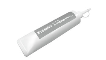
Note) JWGS100G is separately sold in a 100g container. (Click here. )

*The product names mentioned above are trademarks or registered trademarks of each manufacturer.

×
(Drag to move. )

Ideal for maintenance of Linipower Jack and Power Cylinder!

JWGS100G

(100g filled )

Model No. :JWGS100G

Table 2 Lubrication cycle

Lubrication cycle
Traveling distance Every 5km
Frequency of use 100 times or more/day 1 months to 3 months
11 to 100 cycles/day 3 months to 6 months
~10 cycles/day 6 mo.s to 1 yr.

Note) The above values are for longer use, and do not indicate the life.

Greasing on Reduction part

Grease has been applied on the tooth surfaces in advance, therefore, use the decelerating part as it is.

Initial tooth surface application grease

  • Planetary gear (Straight type ):Moly gear grease No. 1 (SUMICO LUBRICANT CO., LTD. )
  • Helical gear (Parallel type ):Moly gear grease No. 1 (SUMICO LUBRICANT CO., LTD. )

※No greasing is required within the expected traveling distance for each basic G Series size. For more information, please contact us separately.