技術資料 直動機器 パワーシリンダ選定
選定:Gシリーズ
必要条件
使用機械と使用法
推力または荷重 N{kgf}
ストローク mm
速度 mm/s
使用頻度 起動回数/min
使用時間(時/日)と年間稼働日数(日/年)
使用機械の負荷の性質
使用環境
電源電圧、周波数
選定手順
機種の決定 STEP1
使用環境基準と使用方法などからタイプ(A、B or C)を決めてください。
形番の決定 STEP2
- (1) ストローク、使用頻度、使用時間から年間走行距離を求めます。
年間走行距離 km = 実ストローク m×使用頻度 回/日×稼働日数/年×10-3
- (2) 負荷の性質と使用機械より、表1を参照し使用係数を求めます。
- (3) 推力、または荷重に使用係数を乗じて補正推力を求めます。
- (4) 補正推力と年間走行距離から、本ページ下の「期待走行距離」より枠番を決定の上、ストローク、速度、電源電圧・周波数をもとに標準機種一覧(こちら)から適用形番を選んでください。
表1 使用係数
| 負荷の性質 | 使用機械例 | 使用係数 |
|---|---|---|
| 衝撃のない円滑な作動 慣性小 |
ダンパ、バルブの開閉 コンベヤ切替装置 |
1.0~1.3 |
| 軽い衝撃のある作動 慣性中 |
ホッパゲートの開閉、各種移載装置、各種リフタ昇降 | 1.3~1.5 |
| 大きな衝撃、振動のある作動 慣性大 |
台車による重量物搬送、ベルトコンベヤ用バッファ、大形蓋の反転開閉装置 | 1.5~3.0 |
注)上記使用係数は一般的な目安であり、使用条件を考慮して決定ください。
特性の確認 STEP3
- (1) 使用頻度は、許容使用頻度(表2)以下で使用してください。
- (2) 負荷時間率を確認してください。
- (3) 惰行距離と停止精度は下記の表3で確認してください。
表2 許容使用頻度
| シリーズ名 | LPG |
|---|---|
| 許容起動頻度 | 10回/分以下 |
| 負荷時間率(%ED) | 25 |
注)負荷時間率は10分間を基準として、10分間当りの運転時間の割合とします。
パワーシリンダGシリーズの許容使用頻度は、上表の起動回数と負荷時間率を満足する範囲です。負荷時間率は次式であらわされます。
負荷時間率(%ED) = 1サイクルの運転時間 1サイクルの運転時間 + 休止時間 ×100%
表3 惰行距離と停止精度(参考値)(リレータイムラグを0.03sと仮定した場合)
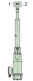
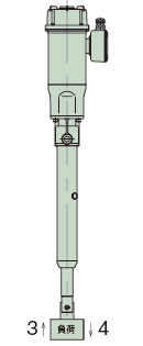
| 形番 | 使用方法 | ||||||||
|---|---|---|---|---|---|---|---|---|---|
| 押上げ荷重(1、3の時) | 吊下げ荷重(2、4の時) | ||||||||
| 50Hz | 60Hz | 50Hz | 60Hz | ||||||
| 惰行距離 | 停止精度 | 惰行距離 | 停止精度 | 惰行距離 | 停止精度 | 惰行距離 | 停止精度 | ||
| LPGA070 LPGB070 LPGC070 |
L | 6.9 | ±0.4 | 10.0 | ±0.5 | 10.6 | ±0.4 | 14.9 | ±0.5 |
| M | 15.0 | ±1.1 | 21.5 | ±1.3 | 21.8 | ±1.2 | 30.1 | ±1.4 | |
| H | 15.4 | ±1.4 | 21.7 | ±1.7 | 23.7 | ±1.5 | 32.7 | ±1.8 | |
| U | 34.2 | ±2.8 | 47.9 | ±3.4 | 60.6 | ±3.1 | 81.2 | ±3.8 | |
| LPGA100 LPGB100 LPGC100 |
L | 6.1 | ±0.4 | 9.0 | ±0.5 | 10.6 | ±0.4 | 14.9 | ±0.5 |
| M | 13.8 | ±1.1 | 19.8 | ±1.3 | 22.1 | ±1.2 | 30.5 | ±1.4 | |
| H | 14.1 | ±1.4 | 19.8 | ±1.7 | 23.8 | ±1.5 | 32.7 | ±1.8 | |
| U | 32.0 | ±2.8 | 45.0 | ±3.4 | 66.9 | ±3.1 | 88.2 | ±3.8 | |
| LPGA150 LPGB150 LPGC150 |
L | 4.6 | ±0.4 | 6.6 | ±0.5 | 7.1 | ±0.4 | 9.8 | ±0.5 |
| M | 10.6 | ±1.1 | 14.7 | ±1.3 | 15.6 | ±1.2 | 21.3 | ±1.4 | |
| H | 13.7 | ±1.4 | 19.0 | ±1.7 | 21.8 | ±1.6 | 30.0 | ±1.9 | |
| LPGA300 LPGB300 LPGC300 |
L | 3.3 | ±0.4 | 4.6 | ±0.5 | 5.1 | ±0.4 | 6.9 | ±0.5 |
| M | 8.6 | ±0.8 | 12.4 | ±0.9 | 23.2 | ±0.8 | 29.4 | ±1.0 | |
| H | 9.4 | ±1.0 | 13.1 | ±1.2 | 19.0 | ±1.1 | 25.0 | ±1.3 | |
※上表値は機種により若干異なります。
注)実際の作動ではロッドの回転防止が必要です。
惰行距離:リミットスイッチ、または停止ボタンが作動して停止するまでの距離を示します。この惰行距離は、荷重のかかり方、操作回路によって変化します。
停止精度:停止を繰り返したときの停止位置のバラツキ量を示します。上表ではリレーおよびブレーキのタイムラグに±25%を見込んでいます。
寿命の目安
台形ネジ仕様の期待走行距離
シリンダ(ナット)の走行距離で25km
※高頻度運転の場合、早期に寿命に達する場合がありますので、期待寿命を満足されているかご確認ください。
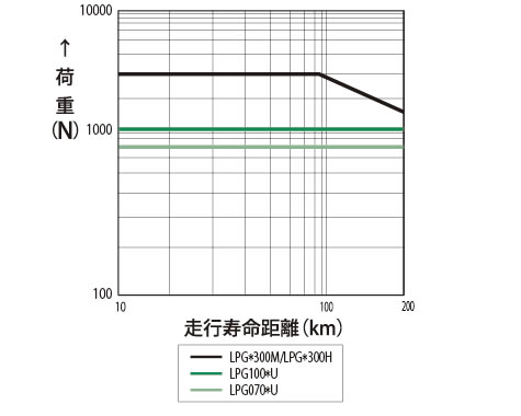
ボールネジ仕様の期待走行距離
ボールネジの寿命は、転動面の疲労による剥離により決まります。この期待走行距離グラフで概略の寿命をご確認ください。ただし、衝撃の多い場合、適正な潤滑やメンテナンスのなされていない場合は大幅に期待走行距離は短くなります。
期待走行距離(km) = 実負荷ストローク(m)×使用頻度(回/日)×稼働日数 / 年×10-3×期待年数
右のグラフは、L10寿命を基準としています。L10寿命とは、全体の90%以上が達成できる寿命を走行距離で表したものです。寿命を基準に、パワーシリンダを選定される場合は、このグラフより形番をお選びください。
負荷がストロークの途中にて大きく変動する場合には、下式にて等価荷重(PM)を算出してください。
PM = PMIN + 2×PMAX 3
PM:等価荷重N{kgf}
PMIN:最小荷重N{kgf}
PMAX:最大荷重N{kgf}
期待走行距離
選定時の注意事項:Gシリーズ
ブレーキの保持力
パワーシリンダGシリーズの停止時における荷重保持力は、定格推力以上発揮しますので定格荷重の保持に使用できます。この保持力は、ブレーキ付モータのブレーキ作用により発生します。ブレーキは停止中、常にスプリング力でブレーキ作用をするスプリング制動式で、ブレーキトルクはモータ定格トルクの150%以上の保持力があります。
※パワーシリンダを選定される場合、使用荷重(静時・動時)は、定格推力を超えないように安全率を見込んだ十分な推力のパワーシリンダをお選びください。
ブレーキ停止
この方法は、リミットスイッチまたは停止ボタン操作でブレーキを作動・停止させ、ストローク上・下限、中間停止など、多段の位置決めができます。作動速度や負荷により惰行量や停止精度が異なります。
正確な位置決めをしたいときや作動速度の速いものは、ブレーキ別切りにすることをおすすめします。リミットスイッチの設定は惰行距離を見込んで停止信号を与えてください。
参考値を上記表3に示します。
Cタイプの押付停止許容回数
高頻度で押付(引付)停止をする場合
1日10回以上の頻度でご使用になる場合には、当社までお問合せください。
- 注)
1.押付(引付)停止でご使用になる場合にはブレーキ部の結線は別切りを推奨します。 - 2.押付(引付)停止でご使用になる場合、相手装置の強度は定格推力の250%以上としてください。
- 3.H・U速での押付(引付)停止はインバータによる減速停止をしてください。詳しくは当社までお問合せください。
水平駆動時の許容質量
ダンパやホッパゲートの開閉や通常の反転、傾斜、昇降などでは起動時に安全装置は働くことはありませんが、台車の水平移動など慣性が大きい場合には起動時に安全装置が働き、スムーズに作動が行なわれない場合があります。各機種毎の許容質量mは、表4をご参照ください。
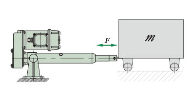
- 台車質量:mkg
- 摩擦係数:μ
- 台車走行抵抗:= μm ≦ 定格推力
表4 許容質量 m
| パワーシリンダ形番 | LPGA070 LPGB070 LPGC070 |
LPGA100 LPGB100 LPGC100 |
LPGA150 LPGB150 LPGC150 |
LPGA300 LPGB300 LPGC300 |
|
|---|---|---|---|---|---|
| 速度 | L | 1150 | 2085 | 1220 | 2060 |
| M | 170 | 280 | 310 | 1560 | |
| H | 130 | 240 | 270 | 790 | |
| U | 71 | 102 | - | - | |
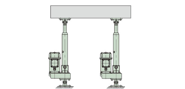
連動運転方法
パワーシリンダは、図1のように数台のパワーシリンダに荷重分担させて搬送、昇降作業ができます。これは負荷変動による速度変化が少ないためです。
選定にあたって右の項目に注意してください。
図1 数台のパワーシリンダによる連動運転
制御方法
始動は全数同時に電源を入れ、停止はそれぞれのパワーシリンダについたリミットスイッチで行ってください。1個のリミットスイッチで全数を制御しますとストロークの累積誤差が生じますから避けてください。
連動精度
作動中の各パワーシリンダの速度変動は、負荷変動により生じ一般には5%程度です。停止時のバラツキは、上記表3の停止精度をご参照ください。同期をされる場合はマルチ仕様をご使用ください。
1台当りの推力 必要推力 N{kgf} パワーシリンダ使用数×連動係数
表5 連動係数
| パワーシリンダ使用数 | 2台 | 3台 | 4台 | 5台 | 6台 |
|---|---|---|---|---|---|
| 連動係数 | 0.8 | 0.7 | 0.6 | 0.55 | 0.5 |
シリンダ使用ストロークが短い場合、高速タイプのシリンダは1ストローク当たりの運転時間が短くなるため、実際上制御が困難となり使用できません。以下にモータ通電時間を0.5sとしたときの最小必要ストロークを示しますので、これを参考に速度を決定してください。
| 速度記号 | H | U |
|---|---|---|
| 称呼速度 mm/s 50/60Hz | 100/120 | 200/240 |
| 0.5s 運転時移動距離 mm | 50/60 | 100/120 |
| 予想最大惰行距離 mm(参考) | 24/33 | 67/89 |
| 最小必要ストローク mm | 74/93以上 | 167/209以上 |
※表の数値は50Hz時/60Hz時の値をあらわしています。
