技術資料 直動機器 パワーシリンダ 取扱
選定時の注意事項(エコシリーズ・CDSタイプ)
- ・標準仕様のシリンダには回り止め機構は付いていません。先端部をフリーの状態でご使用の場合は、ロッド回り止め仕様(オプション)をご選定ください。
また、磁気センサ付(オプション)の場合は、必ずロッド回り止め仕様が必要です。 - ・選定したシリンダの起動回数が許容値以内であるかどうか、こちらの許容起動回数表をご参照ください。
- ・本シリンダを押付または引付停止で使用の場合、相手装置側の強度は定格推力の300%以上としてください。
- ・パワーシリンダは屋内形構造になっています。錆の発生などの問題がありますので屋内の環境の良い場所に保管してください。湿気には十分ご注意ください。急激な温度変化のある場所に設置しますと結露が生じ、故障や錆の原因になりますのでご注意ください。
- ・腐食性雰囲気の中での保管や使用はしないでください。また、引火性雰囲気での使用はできません。
- ・密閉した容器内など放熱が期待できない場所での使用は故障の原因となりますので使用しないでください。
据付時の注意事項(エコシリーズ・CDSタイプ)
- ・本体の据付けはトラニオンマウントまたはフランジマウントにてご使用ください。トラニオンマウントで揺動を伴うご使用の場合には、I形先端金具またはU形先端金具をお選びください。
- ・横荷重が加わる場合は、ガイドを設けて直接横荷重や曲げモーメントを受けないようにしてください。
- ・トラニオンマウントで取付ける場合は水平および垂直取付け可能です。
- ・フランジマウントで取付ける場合は、垂直方向で取付けてください。 (右図参照)
- ・長ストロークでかつ水平でご使用の場合、右図のように、別途フレーム先端下部を支持してください。その際、フレームと支持ベースは固定しないでください。
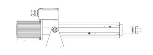
トラニオンマウント
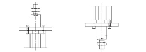
フランジマウント
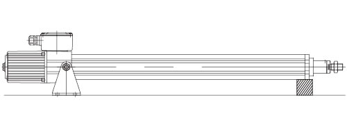
フレーム先端支持 (固定不可)
使用上の注意事項(エコシリーズ・CDSタイプ)
- ・押付または引付停止時にモータは停止しますが、端子台上は通電状態となっています。端子箱を開けて作業をする場合、必ず主電源を切ってください。
- ・手動でストロークを調整する場合、モータの反負荷側のキャップボルトを取外し、手動軸をマイナスドライバなどで回転させてください。ただし、ブレーキがかかった状態での操作となりますので、あくまでも緊急用としてご使用ください。また、手動操作の際は必ず負荷を取除いてください。
- ・インバータは絶対に使用しないでください。本シリンダは端子箱に内蔵のCDSにより過電流を検知し、モータを停止し、押付力を制御していますので、インバータを使用されますとCDS回路が破損します。
- ・本シリンダはメガテスト厳禁です。内蔵のCDSを破損するおそれがあります。外部回路のメガテストを行う場合、端子箱の全端子を外してください。
- ・前進・後退の切替えは、0.2秒以上間隔をあけて行ってください。
- ・運転中および停止直後はモータ部周辺の温度がかなり上昇しているおそれがありますので、モータ部周辺には絶対に触らないでください。
参考回路図

NOTE:
- 1.本図は単動回路図です。この回路図では、ストレート、パラレルともPBFにより前進します。
- 2.PBFによりシリンダが前進して、ストロークエンド端またはストローク途中の壁等に衝突した場合、押付力を出して自動停止します。後退する場合、PBRによりシリンダが後退して前進側と同様に停止します。シリンダが停止するごとにMCF・MCRはOFFとなる回路としてください。
- 3.シリンダ端子台のRUN・COM端子からシリンダが動作中の出力信号を取出せます。
オープンコレクタ出力 MAX.50mA DC30V
リレーARのコイル電流はDC50mA以下をご使用ください。 - 4.電磁接触器は富士電機製のSC-O相当以上の接点容量のものをご使用ください。
- 5.ブレーキ・モータ電流値(ブレーキは内部結線済)
形番 モータ定格電流値(A) モータ拘束電流値(A) 200V 50Hz 200V 60Hz 220V 60Hz 200V 50Hz 200V 60Hz 220V 60Hz LPE025HT(HK) 0.6 0.6 0.6 1.0 0.9 1.0 LPE050LT(LK) 0.6 0.6 0.6 1.0 0.9 1.0 LPE050HT(HK) 1.1 1.1 1.1 2.1 1.9 2.1 LPE100LT(LK) 1.2 1.3 1.2 2.1 1.9 2.1
注)モータ定格電流値はブレーキ電流(0.11A)を含み、 シリンダ端子箱のU・W相の値です。モータ銘板の電流値とは異なりますのでご注意ください。
