技術資料 直動機器 パワーシリンダ選定
選定:エコシリーズ・サーボタイプ
入力軸慣性モーメント
| 基本形番 | 減速機 サイズ |
ストローク毎の慣性モーメント×10-4kg・m2 | |||||
|---|---|---|---|---|---|---|---|
| 100 | 200 | 300 | 400 | 500 | 600 | ||
| LPES15F | - | 0.086 | 0.102 | 0.119 | - | - | - |
| LPES30F | - | 0.134 | 0.151 | 0.168 | - | - | - |
| LPES30R3 | 042 | 0.045 | 0.047 | 0.049 | - | - | - |
| LPES30R4 | 0.038 | 0.039 | 0.041 | - | - | - | |
| LPES30R5 | 0.035 | 0.036 | 0.037 | - | - | - | |
| LPES30R7 | 0.033 | 0.033 | 0.033 | - | - | - | |
| LPES30R9 | 0.032 | 0.032 | 0.032 | - | - | - | |
| LPES30RA | 0.031 | 0.032 | 0.032 | - | - | - | |
| LPES150F | - | 1.039 | 1.166 | 1.292 | 1.418 | 1.545 | 1.671 |
| LPES150R3 | 060 | 0.275 | 0.290 | 0.304 | 0.318 | 0.332 | 0.346 |
| LPES150R4 | 0.205 | 0.213 | 0.221 | 0.229 | 0.237 | 0.244 | |
| LPES150R5 | 0.172 | 0.177 | 0.182 | 0.187 | 0.192 | 0.197 | |
| LPES150R7 | 0.151 | 0.154 | 0.156 | 0.159 | 0.162 | 0.164 | |
| LPES150R9 | 0.143 | 0.144 | 0.146 | 0.148 | 0.149 | 0.151 | |
| LPES150RA | 0.140 | 0.142 | 0.143 | 0.144 | 0.145 | 0.147 | |
| LPES300F | - | 1.720 | 1.846 | 1.973 | 2.099 | 2.225 | 2.352 |
| LPES300R3 | 060 | 0.351 | 0.365 | 0.379 | 0.393 | 0.407 | 0.421 |
| LPES300R4 | 0.247 | 0.255 | 0.263 | 0.271 | 0.279 | 0.287 | |
| LPES300R5 | 0.199 | 0.204 | 0.209 | 0.214 | 0.219 | 0.224 | |
| LPES300R7 | 0.165 | 0.168 | 0.170 | 0.173 | 0.175 | 0.178 | |
| LPES300R9 | 0.151 | 0.153 | 0.154 | 0.156 | 0.157 | 0.159 | |
| LPES300RA | 0.147 | 0.148 | 0.150 | 0.151 | 0.152 | 0.154 | |
| LPES300R3 | 075 | 0.801 | 0.815 | 0.829 | 0.843 | 0.857 | 0.871 |
| LPES300R4 | 0.587 | 0.595 | 0.603 | 0.611 | 0.619 | 0.627 | |
| LPES300R5 | 0.539 | 0.544 | 0.549 | 0.554 | 0.559 | 0.564 | |
| LPES300R7 | 0.485 | 0.488 | 0.490 | 0.493 | 0.495 | 0.498 | |
| LPES300R9 | 0.461 | 0.463 | 0.464 | 0.466 | 0.467 | 0.469 | |
| LPES300RA | 0.457 | 0.458 | 0.460 | 0.461 | 0.462 | 0.464 | |
| 基本形番 | 減速機 サイズ |
ストローク毎の慣性モーメント×10-4kg・m2 | ||||||
|---|---|---|---|---|---|---|---|---|
| 200 | 300 | 400 | 500 | 600 | 800 | 1000 | ||
| LPES1500F | - | 12.513 | 13.155 | 13.797 | 14.438 | 15.080 | 16.363 | 17.647 |
| LPES1500R3 | 075 | 2.000 | 2.072 | 2.143 | 2.214 | 2.286 | 2.428 | 2.571 |
| LPES1500R4 | 1.262 | 1.302 | 1.342 | 1.382 | 1.423 | 1.503 | 1.583 | |
| LPES1500R5 | 0.971 | 0.996 | 1.022 | 1.048 | 1.073 | 1.125 | 1.176 | |
| LPES1500R7 | 0.705 | 0.718 | 0.732 | 0.745 | 0.758 | 0.784 | 0.810 | |
| LPES1500R9 | 0.594 | 0.602 | 0.610 | 0.618 | 0.626 | 0.642 | 0.658 | |
| LPES1500RA | 0.565 | 0.572 | 0.578 | 0.584 | 0.591 | 0.604 | 0.616 | |
| LPES1500R3 | 100 | 4.640 | 4.712 | 4.783 | 4.854 | 4.926 | 5.068 | 5.211 |
| LPES1500R4 | 3.522 | 3.562 | 3.602 | 3.642 | 3.683 | 3.763 | 3.843 | |
| LPES1500R5 | 3.211 | 3.236 | 3.262 | 3.288 | 3.313 | 3.365 | 3.416 | |
| LPES1500R7 | 2.875 | 2.888 | 2.902 | 2.915 | 2.928 | 2.954 | 2.980 | |
| LPES1500R9 | 2.724 | 2.732 | 2.740 | 2.748 | 2.756 | 2.772 | 2.788 | |
| LPES1500RA | 2.695 | 2.702 | 2.708 | 2.714 | 2.721 | 2.734 | 2.746 | |
| LPES1500R3 | 140 | 11.000 | 11.072 | 11.143 | 11.214 | 11.286 | 11.428 | 11.571 |
| LPES1500R4 | 8.547 | 8.587 | 8.627 | 8.667 | 8.708 | 8.788 | 8.868 | |
| LPES1500R5 | 8.065 | 8.090 | 8.116 | 8.142 | 8.167 | 8.219 | 8.270 | |
| LPES1500R7 | 7.469 | 7.482 | 7.495 | 7.508 | 7.521 | 7.547 | 7.574 | |
| LPES1500R9 | 7.239 | 7.247 | 7.255 | 7.263 | 7.271 | 7.286 | 7.302 | |
| LPES1500RA | 7.191 | 7.198 | 7.204 | 7.210 | 7.217 | 7.230 | 7.242 | |
注)慣性モーメントには、サーボモータの慣性モーメントは含んでいません。
許容使用頻度と負荷時間率
負荷時間率は30分間を基準として30分間あたりの運転時間の割合とします。
負荷時間率は右式で計算します。
エコシリーズ サーボタイプの許容起動回数はモータの発熱およびボールネジ・ベアリング部の発熱により決まります。使用ストローク、使用推力により異なりますので、上記値は目安値としてください。また、シリンダの寿命を考慮した値ではありません。ただし、サーボモータは定格内での運転を条件とします。
| 起動回数 | 15回/分 |
|---|---|
| 負荷時間率 | 50%ED |
※通常屋内とは、風雨・水がかからず、塵埃は一般工場内レベルを指します。
負荷時間率(%ED) = 1サイクルの運転時間 1サイクルの運転時間 + 休止時間 ×100
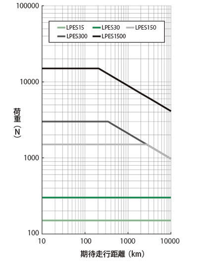
寿命
ボールネジの寿命は、転動面の疲労による剥離により決まります。この期待走行距離グラフで概略の寿命をご確認ください。ただし、衝撃の多い場合、適正な潤滑やメンテナンスのなされていない場合は大幅に期待走行距離は短くなります。
期待走行距離(km) = 実負荷ストローク(m)×使用頻度(回/日)×稼働日数 / 年×10-3×期待年数
右のグラフは、L10寿命を基準としています。
L10寿命とは、全体の90%以上が達成できる寿命を走行距離で表したものです。
寿命を基準に、パワーシリンダを選定される場合は、このグラフより形番をお選びください。
例えば、期待走行距離を1000km、実荷重を5000N{510kgf}とした場合、求められるパワーシリンダは、LPES1500になります。
※サーボモータの容量は、マウントコード表より、「実荷重<発生推力」となるよう選定してください。
負荷がストロークの途中にて大きく変動する場合には、下式にて等価荷重(PM)を算出してください。
また、LPES30以下では、期待走行距離は10000km以上となります。
PM = PMIN + 2×PMAX 3
PM:等価荷重N{kgf}
PMIN:最小荷重N{kgf}
PMAX:最大荷重N{kgf}
期待走行距離