技術資料 減速機 サーボモータ用減速機TERVO 選定
選定手順や注意事項等をご覧になりたい方は下記へお進みください。
製品シリーズの絞り込みや仮選定をご希望の方は
こちらをクリックしてください。
使用条件が決まっており詳細な選定をご希望の方は
こちらをクリックしてください。
選定
1. 条件
(1) 運転サイクル
出力軸回転速度
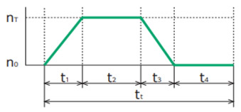
- nT:出力軸最高回転速度(r/min)
- t1:加速時間(sec)
- t2:定常時間(sec)
- t3:減速時間(sec)
- t4:停止時間(sec)
- tt:1サイクルの時間(sec.)
出力トルク
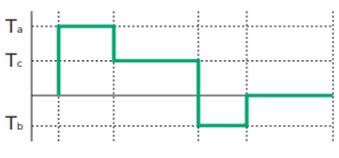
- Ta:加速トルク(N・m)
- Tc:定常トルク(N・m)
- Tb:減速トルク(N・m)
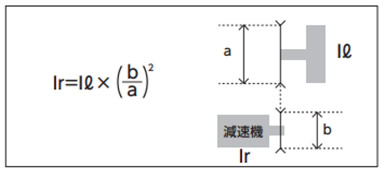
(2) 負荷慣性モーメント Ir
慣性モーメントの求め方の表より減速機の出力軸上の負荷慣性モーメントIrを算出
Ir:減速機出力軸上負荷慣性モーメント(kg・m2)
(3) 加減速トルク Ta, Tb
加速トルク Ta = △Ta + Tc
減速トルク
△Ta = 2πIr × △na 60 × t1
Tb = △Tb - Tc
△Tb = 2πIr × △nb 60 × t3
- Ir:減速機出力軸上負荷慣性モーメント(kg・m2)
- △Ta:慣性加速トルク(N・m)
- △na:回転速度差(r/min) △na = nT - no
- △Tb:慣性減速トルク(N・m)
- △nb:回転速度差(r/min) △nb = nT - no
(4) 定常トルク Tc
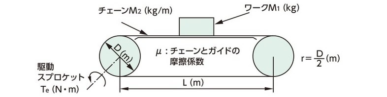 |
Tc = G(M1 + 2.1 × M2 × L) × μ × r G = 重力加速度:9.80665m/s2 |
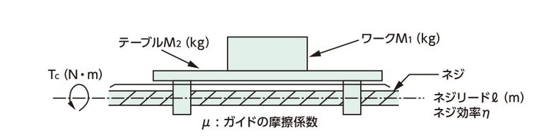 |
Tc = G(M1 + M2) × μ × ℓ 2 × π × η |
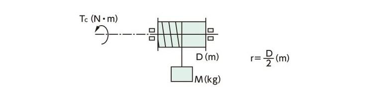 |
Tc = GM × r |
2. 選定手順
| (1) 減速比 i を算出 |
i ≒
Nm
nT
Nm:モータ回転速度 |
|||||||||||||||||
| ↓ | ||||||||||||||||||
| (2) 平均出力トルクを算出 |
|
|||||||||||||||||
| ↓ | ||||||||||||||||||
| (3) サイズの決定
平均トルク 最大トルク |
fs:シリーズ係数
GMTK・HMTK:1.4 EWJMK・EWMK・SWJMK・SWMK:1.0 |
|||||||||||||||||
| ↓ | ||||||||||||||||||
| (4) 平均出力軸回転速度nave.を算出 |

|
|||||||||||||||||
| ↓ | ||||||||||||||||||
| (5) 回転速度の確認 nave. × i < 減速機定格入力回転速度 nT × i < 減速機最高入力回転速度 |
|
|||||||||||||||||
| ↓ | ||||||||||||||||||
| (6) 負荷時間率の確認 ウォームギヤヘッドのみ
負荷時間率 %ED = t1 + t2 + t3 tt × 100 %ED < 50% かつ t1 + t2 + t3 < 20min. |
||||||||||||||||||
| ↓ | ||||||||||||||||||
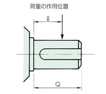
| (7) 出力軸ラジアル荷重の確認 | O.H.L < N:減速機許容ラジアル荷重※ O.H.L = 2000 × Ta × f × Lf D D:スプロケットなどのピッチ円直径(mm) |
|||||||||||||||||
※伝動能力表の許容ラジアル荷重をご参照ください。
f:O.H.L.係数
| チェーン | ギヤ歯付ベルト | Vベルト |
|---|---|---|
| 1.0 | 1.25 | 1.5 |
Lf:作用位置係数
| ℓ/Q | 0.25 | 0.38 | 0.5 | 0.75 | 1 |
|---|---|---|---|---|---|
| Lf | 0.8 | 0.9 | 1 | 1.5 | 2 |
中空出力軸
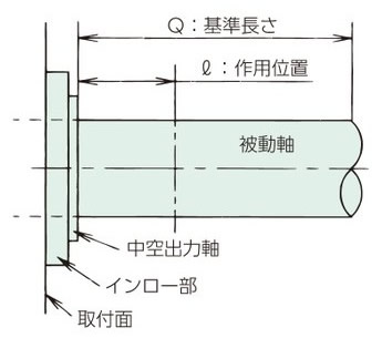
Q:基準長さは左表をご参照ください。
中実出力軸
Q:基準長さは各タイプの寸法表をご参照ください。
基準長さ:Q 中空出力軸の場合
HMTK
| 形番 | 速比 | Q |
|---|---|---|
| HMTK0220H | 5 ~ 60 | 36 |
| HMTK0230H | 80 ~ 200 | 42 |
| HMTK0430H | 5 ~ 50 | |
| HMTK0435H | 60 ~ 200 | 58 |
| HMTK0735H | 5 ~ 50 | |
| HMTK0745H | 60 ~ 200 | |
| HMTK1545H | 5 ~ 80 | 66 |
| HMTK2245H | 5 ~ 60 | |
| HMTK1555H | 100 ~ 200 | |
| HMTK2255H | 80 ~ 120 | 82 |
| HMTK3755H | 5 ~ 60 | |
| HMTK5555H | 5 ~ 60 |
SWJMK, SWMK
| 形番 | 速比 | Q |
|---|---|---|
| SWJMK35 | 10 ~ 60 | 20 |
| SWJMK42 | 10 ~ 60 | 25 |
| SWJMK50 | 10 ~ 60 | 30 |
| SWJMK63 | 10 ~ 60 | 35 |
| SWJMK70 | 10 ~ 60 | 40 |
| SWMK80 | 10 ~ 60 | 50 |
| SWMK100 | 10 ~ 60 | 55 |
