技術資料 トップチェーン 取扱
4-1. スプロケットの取扱
プラスチックモジュラーチェーンに使用する駆・従動シャフトは、特殊な例(固定幅タイプ、TODとの直交など)を除き一般的に角シャフトを推奨します。
チェーンは、温度変化により膨張・収縮しますのでスプロケットが幅方向に横移動できるようにフリーに取り付けます。
ただし、チェーンの蛇行防止の為、駆・従動シャフトとも、中央部1個(または2個)のスプロケットをセットスクリュまたはセットカラー、六角穴付ボルトで固定します。
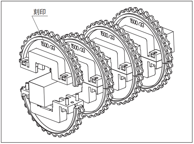
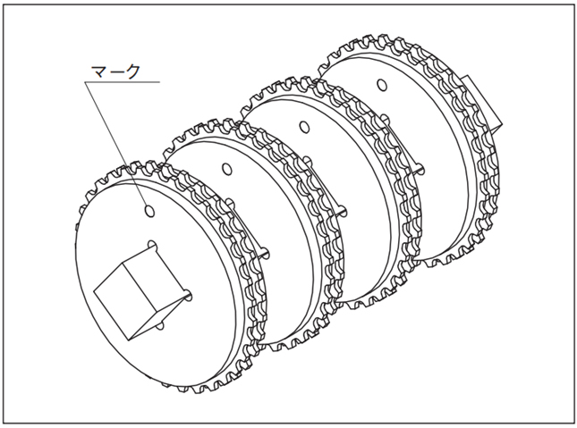
角シャフトにスプロケットを取り付ける際には、刻印やマークを目安にして向きや歯の位置を一定に合わせてください。
4-1-1. スプロケットの位相合わせ
刻印やマークを合わせてシャフトに取付けてください。
分割形スプロケット
一体形スプロケット
4-1-2. チェーンの膨張・収縮
プラスチックモジュラーチェーンは樹脂製ですので、温度変化により膨張・収縮します。
チェーンの線膨張率の目安は、20℃を基準として12×10-5(/℃)です。
呼称幅の膨張量(⊿W)は下式により求められます。
⊿W = チェーン呼称幅 × (使用雰囲気温度 - 20) × 12 × 10-5
(例) K60(1524mm)のチェーンが20℃から60℃まで温度が上昇する雰囲気で使用する場合
⊿W = 1524 × (60 - 20) × 12 × 10-5 = 7.3mm
4-1-3. スプロケットの固定
スプロケットはチェーンとコンベヤの線膨張差、チェーンとスプロケットの据付誤差を吸収するため、シャフトとはルーズフィットとしていますが、チェーンの蛇行を防止するため中央付近の1つのスプロケットの両側に約0.5mm(WTの場合:1.6mm)のスキマをあけて、セットスクリュや六角穴付ボルト、セットカラーを取付けます。
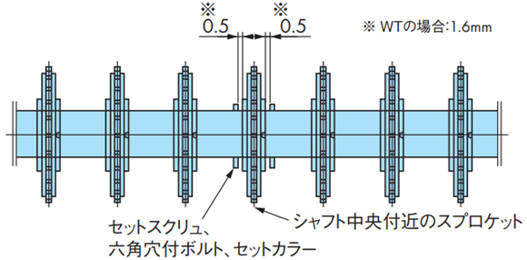
※蛇行防止アタッチメント(タブ)ありチェーンを使用の場合は、蛇行防止アタッチメント間に取付けるスプロケットを固定してください。
4-1-4. チェーンの取付け
スプロケットのピッチを所定の取付ピッチに合わせ、チェーンを巻付けます。
⚠
スプロケットの取付ピッチがずれると、チェーンがスプロケットに乗上げ破損する場合があります。確実に確認してください。
