技術資料 トップチェーン 取扱
4-3. スプロケットの取付ピッチの決定
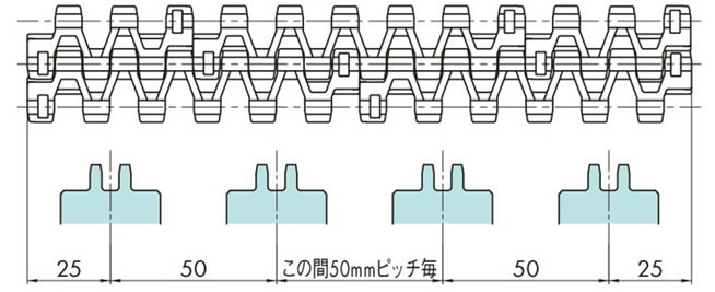
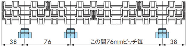
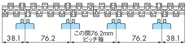
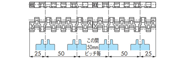
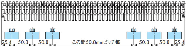
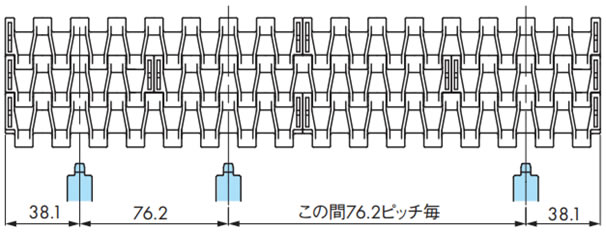
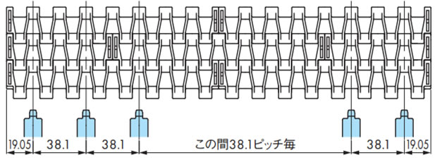
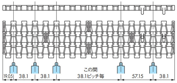
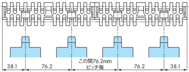
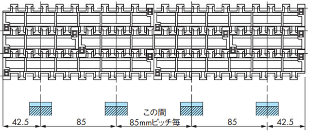
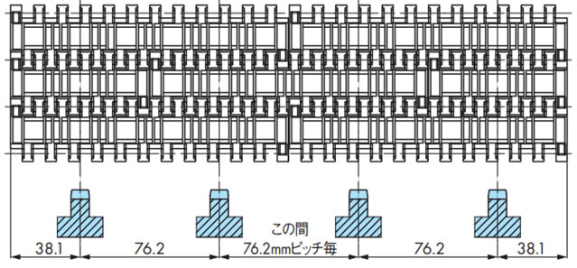
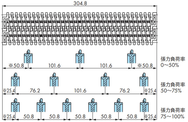
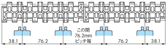
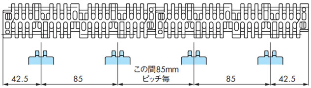
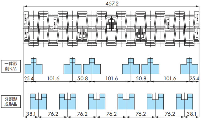
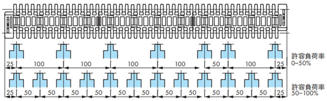
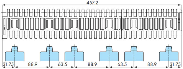
各チェーンのスプロケットの取付けピッチ図を下記に示します。
手順6の(2)式で求めたチェーン幅1m換算張力F'がチェーンの許容張力(幅1m当たりのMAX)の何%のレベルかを確認します。
チェーン張力負荷率F1により変わる場合もありますので、ご注意ください。
張力負荷率F1(%)の計算
F1 = 100F' A ...(3)
F'...手順6で求めたチェーン幅1m換算能力 kN/m{kgf/m}
A...各使用温度におけるチェーン幅1m換算能力 kN{kgf}
チェーン能力線図を参照ください。
幅広タイプ
(1) WT0405-W形
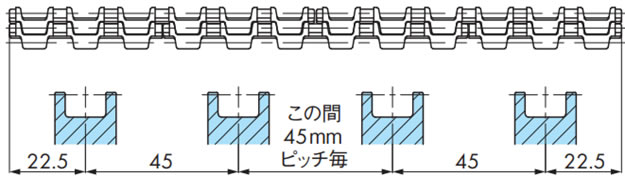
(2) WT0705-W形
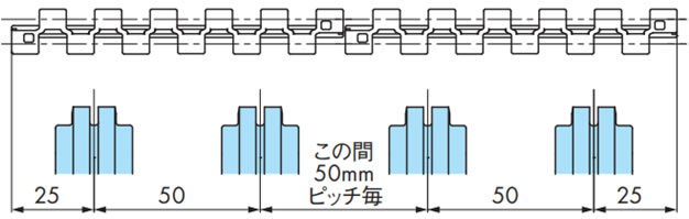
(3) BTN5形、BTN5-A形
注)BTN5-A(蛇行防止アタッチメントあり)には、スプロケットBT5-24Tは使用できません。BT5-32Tをご検討ください。WT-SW1500-24Tは使用できます。
(4) WT1505-K形、WT1505RN-K形、WT1505G-K形、WT1506-K形
(5) WT1505GTO-K形、WT1505GTORN-K形

(6) WT1515-W形、WT1516-W形、WT1515G-W形、WT1515(T-)F-W形、WT1516(T-)F-W形、WT1515VG-W形
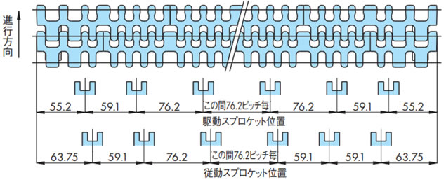
(7) WT1907-K形
注)奇数インチ幅の場合、取付ピッチが1ヵ所76.2mmになります。中央付近で調整ください。
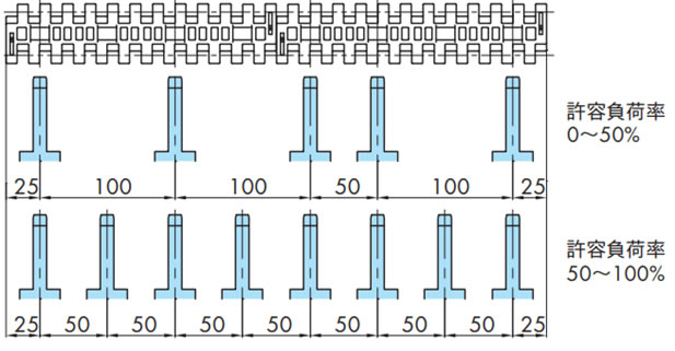
(8)BT6シリーズ、BTC8形、BTC8-A形
・張力負荷率(F1)が50%以下の場合のスプロケット取付ピッチ
(9)BT6シリーズ、BTC8形
・張力負荷率(F1)が50%を超える場合のスプロケット取付ピッチ
(10)BTC8-A形
・張力負荷率(F1)が50%を超える場合のスプロケット取付ピッチ
(11)WT2505-K形、WT2506-K形、BTM8H形
(12)WT2515-W形、WT2515G-W形、WT2515F-W形

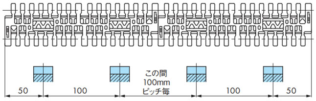
(13)WT2250FG、VG
(14)BTC8S形、WT2525-K形、WT2525VG-K形
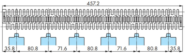
(15)WT2705-K形/WT2706-K形
注)
- 1. ※位置には必ずスプロケットを配置してください。
- 2. 奇数インチ幅の場合、取付ピッチが1ヵ所変則ピッチになります。中央付近で調整ください。
(16)WT3005-K形/WT3005G-K形
(17)WT3086-K形/WT3086G-K形
(18)WTU3015T-K形
注)駆動スプロケットと従動スプロケットで配置が異なります。
(19)WT3109-W形
注)許容負荷率0~50%のスプロケット配置の場合、1ヵ所は50mm配置になります。
(20)WT3816-K形
(21)WT3827-K形
(22)WT3835-K形

(23)WT3835-T形(浮上がり防止アタッチメント(タブ)あり)
(24)BTH16
注)許容負荷率0~50%のスプロケット配置の場合、1ヵ所は50mm配置になります。
(25)WT5707-K形
(26)WT1306-W形