技術資料 ドライブチェーン ローラチェーンの選定
2.選定に使用する係数
多列係数
多列ローラチェーンの伝動能力は、チェーンの各列にかかる荷重が等分されないため、単列ローラチェーンの列数倍の能力は期待できません。
したがって、多列ローラチェーンの伝動能力は、1列ローラチェーンの伝動能力に多列係数を乗じて求めます。
| ローラチェーン列数 | 多列係数 |
|---|---|
| 2列 | 1.7 |
| 3列 | 2.5 |
| 4列 | 3.3 |
| 5列 | 3.9 |
| 6列 | 4.6 |
使用係数 Ks
伝動能力は、負荷変動の少ない場合を条件としていますから、負荷変動の大小により、使用係数Ksで伝動kWを補正するものです。
機械の種類、原動機の種類によって、表2に基づき使用係数Ksを決めます。
伝動kWに使用係数を乗じて、補正kWを求めます。
| 衝撃の種類 | 使用機械例 | 原動機の種類 | ||
|---|---|---|---|---|
| モータ タービン |
内燃機関 | |||
| 流体継手 付 |
流体継手 なし |
|||
| 平滑な伝動 | 負荷変動の少ないベルトコンベヤ、チェーンコンベヤ、 遠心ポンプ、遠心ブロア、一般繊維機械、 負荷変動の少ない一般機械 |
1.0 | 1.0 | 1.2 |
| 多少の衝撃を 伴う伝動 |
遠心圧縮機、舶用推進機、多少負荷変動のあるコンベヤ、 自動炉、乾燥機、粉砕機、一般工作機械、コンプレッサ、 一般土建機械、一般製紙機械 |
1.3 | 1.2 | 1.4 |
| 大きな衝撃を 伴う伝動 |
プレス、クラッシャ、土木鉱山機械、振動機械、 石油さく井機、ゴムミキサー、ロール、ロールガング、 逆転あるいは衝撃荷重のかかる一般機械 |
1.5 | 1.4 | 1.7 |
回転係数 Knと歯数係数 Kz
表3 回転係数 Knと歯数係数 Kz
| 回転速度 r/min | 回転係数 Kn |
|---|---|
| 27未満 | 1.00 |
| 27以上37未満 | 1.03 |
| 37以上50未満 | 1.07 |
| 50以上70未満 | 1.10 |
| 70以上100未満 | 1.14 |
| 100以上150未満 | 1.19 |
| 150以上300未満 | 1.27 |
| 300以上500未満 | 1.34 |
| 500以上1000未満 | 1.44 |
| 1000以上2000未満 | 1.54 |
| 2000以上4000未満 | 1.65 |
| 歯数 | 歯数係数 Kz |
|---|---|
| 9以上12未満 | 1.16 |
| 12以上15未満 | 1.14 |
| 15以上18未満 | 1.12 |
| 18以上24未満 | 1.10 |
| 24以上30未満 | 1.08 |
| 30以上38未満 | 1.06 |
| 38以上47未満 | 1.04 |
| 47以上60未満 | 1.02 |
| 60以上 | 1.00 |
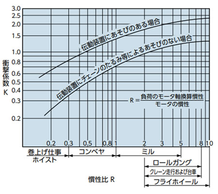
衝撃係数 K
原動機と負荷との同一軸換算における慣性モーメント比(Iの比、GD2の比)、および伝動装置の遊びの大きさにより定まる定数です。
慣性比R > 10のときは、R = 10
慣性比R < 0.2のときは、R = 0.2としてください。
原動機または負荷のIまたはGD2が不明のときは図1のRの値を用いてください。
図1 衝撃係数 K
アンバランス荷重係数 Ku
吊下げ用、台車駆動などでチェーン2本または4本で吊下げ、台車けん引するときは、チェーンの作用張力が均等になりません。
左右のアンバランスの目安として下記アンバランス荷重係数Kuを乗じて1本当りのチェーン作用張力を求めるときに使用します。
(例) 4本吊りでの1本当りのアンバランス荷重係数
Ku = 0.6 × 0.6 = 0.36
| 2本 | 0.6 |
|---|---|
| 4本 | 0.36 |
