技術資料 ドライブチェーン チェーン選定について
選定に必要な計算式
計算式に使用する記号と単位
| 記号 | 説明 | SI単位 | {重力単位} |
|---|---|---|---|
| αb | 負荷の減速度 | m/s2 | m/s2 |
| αs | 負荷の加速度 | m/s2 | m/s2 |
| C | 軸間距離をリンク数で表わしたもの | - | - |
| C′ | 機長 | m | m |
| d | 減速機出力軸スプロケットのピッチ円直径 | mm | mm |
| d1 | 小スプロケットのピッチ円直径 | mm | mm |
| d2 | 大スプロケットのピッチ円直径 | mm | mm |
| D | ドラム外径 | mm | mm |
| Fb | 減速時のチェーン張力 | kN | kgf |
| F'b | 減速時の補正チェーン張力 | kN | kgf |
| FC | 台車駆動のチェーン張力 | kN | kgf |
| F'C | 台車駆動の補正チェーン張力 | kN | kgf |
| Fℓ | 負荷(実荷重)側トルクによるチェーン張力 | kN | kgf |
| F'ℓ | 負荷(実荷重)側トルクによる補正チェーン張力 | kN | kgf |
| Fm | 原動機定格出力(kW)によるチェーン張力 | kN | kgf |
| F'm | 原動機側からの補正チェーン張力 | kN | kgf |
| Fms | 原動機の始動トルクによるチェーン張力 | kN | kgf |
| F'ms | 原動機の始動トルクによる補正チェーン張力 | kN | kgf |
| Fmb | 原動機のブレーキトルクによるチェーン張力 | kN | kgf |
| F'mb | 原動機のブレーキトルクによる補正チェーン張力 | kN | kgf |
| FS | 加速時のチェーン張力 | kN | kgf |
| F'S | 加速時の補正チェーン張力 | kN | kgf |
| FW | 負荷(実荷重)によるチェーン張力 | kN | kgf |
| F'W | 負荷(実荷重)からの補正チェーン張力 | kN | kgf |
| f1 | ローラとレールの摩擦係数(潤滑あり0.14 潤滑なし0.21) | - | - |
| G | 標準重力加速度G = 9.80665m/S2 | - | - |
| i | 速比(例)1/30であればi = 30とする | - | - |
| Iℓ{GD2ℓ} | 負荷の原動機軸換算慣性モーメント | kg・m2 | kgf・m2 |
| Im{GD2m} | 原動機軸の慣性モーメント | kg・m2 | kgf・m2 |
| K | 衝撃係数 | - | - |
| Kn | 回転係数 | - | - |
| Ks | 使用係数 | - | - |
| Ku | アンバランス荷重係数 | - | - |
| Kv | ピンギヤ速度係数 | - | - |
| Kz | 歯数係数 | - | - |
| L | チェーン長さ(リンク数) | - | - |
| m | チェーンの単位質量{重量} | kg/m | kgf/m |
| M{W} | 負荷の質量{重量} | kg | kgf |
| n | チェーン速度を求めるときの小スプロケットの回転速度 | r/min | rpm |
| n1 | 原動機軸の回転速度 | r/min | rpm |
| n2 | 負荷軸の回転速度(従動軸の回転速度) | r/min | rpm |
| P | チェーンピッチ | mm | mm |
| R | 慣性比 | - | - |
| S | RSアタッチメント付チェーンのアタッチメント高さ(ドラム取付面からチェーンピッチ中心までの距離) | mm | mm |
| tb | 減速時間 | s | s |
| tS | 加速時間 | s | s |
| Tb | 原動機のブレーキトルク | %(kN・m) | %(kgf・m) |
| Tmax | 原動機の最大(停動)トルク | %(kN・m) | %(kgf・m) |
| TS | 原動機の始動トルク | %(kN・m) | %(kgf・m) |
| Tℓ | 負荷トルク | kN・m | kgf・m |
| Tm | 作用トルク | kN・m | kgf・m |
| Tn | 原動機の定格トルク | kN・m | kgf・m |
| V | チェーン速度 | m/min | m/min |
| Vℓ | 負荷の速度 | m/min | m/min |
| Z | 大スプロケットの歯数 | - | - |
| Z′ | 小スプロケットの歯数 | - | - |
| ω | 原動機軸の角速度 | rad/min | rad/min |
| ωb | 原動機軸の角減速度 | rad/s2 | rad/s2 |
| ωS | 原動機軸の角加速度 | rad/s2 | rad/s2 |
計算式
- 1. チェーンを含む伝達効率η = 1として、すべての選定をしています。
- 2. 選定に使用する張力や伝動kWは表の13項、14項で計算した値を使用してください。
| 項目 | SI単位 | {重力単位} |
|---|---|---|
|
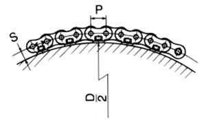
1. チェーン長さ(リンク数):L |
2軸巻掛け伝動のとき
|
|
|
ピンギヤ駆動 |
ドラム外周にアタッチメント付チェーンをドラム外巻きで使用する場合 L = 180° tan-1 P D + 2S
|
|
|
2. チェーン速度:V |
V = P × Z' × n 1000 (m/min) |
|
|
3. 原動機定格出力 (kW), 定格回転速度によるチェーン張力:Fm |
Fm = 60 × kW V (kN) |
Fm = 6120 × kW V (kgf) |
|
4. 負荷の慣性モーメントI(GD2)を |
Iℓ = M × V 2πn1 2 (kg・m2) |
GD2ℓ = W × V πn1 2 (kgf・m2) |
|
5. 原動機の定格トルク:Tn |
Tn = 9.55 × kW n1 (kN・m) |
Tn = 974 × kW n1 (kgf・m) |
|
6. 作用トルク:Tm |
Tm =
Ts(%) + Tmax(%)
2 × 100
× Tn (kN・m) |
Tm =
Ts(%) + Tmax(%)
2 × 100
× Tn (kgf・m) |
|
7. 始動トルクによるチェーン張力:Fms |
Fms =
Ts(%) × i
{d/(2 × 1000)} × 100
× Tn × 1(kN) |
Fms =
Ts(%) × i
{d/(2 × 1000)} × 100
× Tn × 1(kgf) |
|
ブレーキトルクによるチェーン張力:Fms |
Fmb =
Tb(%) × i
{d/(2 × 1000)} × 100
× Tn × 1.2*(kN) *は定数 |
Fmb =
Tb(%) × i
{d/(2 × 1000)} × 100
× Tn × 1.2*(kgf) *は定数 |
8. 加速時間:ts |
ts = (Im + Iℓ) × n1 9550 × (Tm - Tℓ) (s) |
ts = (GD2m + GD2ℓ) × n1 375 × (Tm - Tℓ) (s) |
9. 減速時間:tb ±:吊下げ荷重などのマイナス負荷のときは |
tb = (Im + Iℓ) × n1 9550 × (Tb ± Tℓ) (s) |
tb = (GD2m + GD2ℓ) × n1 375 × (Tb ± Tℓ) (s) |
10. 加速度
直線加速を想定しています。 そうでなければ最大加速度で計算してください。 |
直線運動(負荷の加速度) αs = Vℓ ts × 60 回転運動(原動機軸の角速度) ω = 2π × n1 回転運動(原動機軸の角加速度) ωs = ω ts × 60 |
|
11. 減速度
直線加速を想定しています。 そうでなければ最大減速度で計算してください。 |
直線運動(負荷の減速度) αb = Vℓ tb × 60 回転運動(原動機軸の角速度) ω = 2π × n1 回転運動(原動機軸の角減速度) ωb = ω tb × 60 |
|
12. 加速時のチェーン張力:Fs |
直線運動 Fs = M × αs 1000 + Fw 回転運動 Fs = Iℓ × ωs × i 1000 × d 2 × 1000 + Fw |
直線運動 Fs = M × αs G + Fw 回転運動 Fs = GD2ℓ/4 × ωs × i d 2 × 1000 × G + Fw |
減速時のチェーン張力:Fb |
直線運動 Fb = M × αb 1000 + Fw 回転運動 Fb = Iℓ × ωb × i 1000 × d 2 × 1000 + Fw |
直線運動 Fb = M × αb G + Fw 回転運動 Fb = GD2ℓ/4 × ωb × i d 2 × 1000 × G + Fw |
13. 補正 kW(一般選定のとき) |
補正 kW = 原動機定格 kW × Ks (kW) | |
14. 補正チェーン張力 |
||
原動機からの補正チェーン張力:F'm |
F'm = Fm × Ks × Kn × Kz (kN) {kgf} | |
始動トルクからの補正チェーン張力:F'ms |
F'ms = Fms × K × Kn × Kz (kN) {kgf} | |
停動トルクからの補正チェーン張力:F'mb |
F'mb = Fmb × K × Kn × Kz (kN) {kgf} | |
台車駆動の補正チェーン張力:F'c |
F'c = Fc × Ks × Kn × Kz (kN) {kgf} | |
加速時の補正チェーン張力:F's |
F's = Fs × Kn × Kz (kN) {kgf} | |
減速時の補正チェーン張力:F'b |
F'b = Fb × Kn × Kz (kN) {kgf} | |
負荷からの補正チェーン張力:F'w |
F'w = M × Ks × Kn × Kz × G 1000 (kN) |
F′w = W (またはFw) × Ks × Kn × Kz(kgf) |
|
質量M{重量W}が不明のときは、原動機の定格トルクTnより、軸トルクT = Tn × i (kN・m){kgf・m}を求め、 |
||
15. 慣性比:R |
R = Iℓ Im |
R = GD2ℓ GD2m |
16. 慣性モーメント(I)とはずみ車効果(GD2)の換算 |
1kg・m2...(I) | 4kgf・m2...(GD2) |
上記計算式でのチェーン張力はすべてチェーン1本で使用するときの張力です。
2本以上のチェーンを使用するときは、アンバランス荷重係数 Ku(表4)を乗じて1本当りのチェーン張力を算出します。
アンバランス荷重係数 Ku
吊下げ用、台車駆動などでチェーン2本または4本で吊下げ、台車けん引するときは、チェーンの作用張力が均等になりません。
左右のアンバランスの目安として下記アンバランス荷重係数Kuを乗じて1本当りのチェーン作用張力を求めるときに使用します。
(例) 4本吊りでの1本当りのアンバランス荷重係数
Ku = 0.6 × 0.6 = 0.36
| 2本 | 0.6 |
|---|---|
| 4本 | 0.36 |
