技術資料 ケーブルベヤ - ケーブルベヤの選定 - ケーブルベヤ スチールシリーズの選定
ケーブルベヤ スチールシリーズの選定
TK形・TKH形の場合
ケーブル・ホース収納スぺースによるサイズの決定
TK形、TKH形はサポータ穴(D)をご指定寸法で加工します。
ケーブル・ホースの外径・本数をもとにサポータの最小必要幅B'を計算し、サポータ幅B≧B'のサポータを選定します。
■サポータ寸法
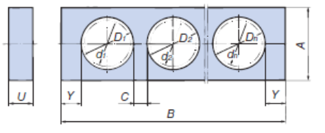
・サポータ穴径の算出
D:サポータ穴径(Φ8以上の整数値) d:ケーブル・ホース外径
・サポータ最小必要幅の算出
B':サポータの最小必要幅 C:4mm以上 Y:下表
| サイズ | Yの最小値 |
|---|---|
| TK070 | 10 |
| TK095 | 15 |
| TK130 | 18 |
| TK180 | 18 |
| TKH250 | 25 |
※サポータ寸法は各商品ページをご参照ください。
・サポータの選定
上記の算出結果と各形式のサポータ寸法よりA・B寸法を選定します。
サポータは移動端側の2リンク目から2リンク毎に取付けます。
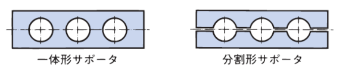
■サポータの一体形と分割形
TK形とTKH形ケーブルベヤには、一体形サポータと分割形サポータの2タイプがあり、分割形サポータは、一方が簡単に取外せるため、支持物の取付け、取外しが容易にできます。口金付ホースや移動距離が長い場合、あるいは支持物の本数が多い場合などにご使用いただくと便利です。
TKS形の場合
■フレーム
仕切板の数量は、最小必要数以上で、できるだけ1ヵ所の穴に1本のケーブル・ホースが入るように決めてください。なお、ケーブル・ホースの配列は左右の質量バランスも考慮してください。
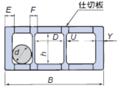
ケーブル・ホースの外径・本数をもとにフレームの最小必要幅B'を計算し、フレーム幅B≧B'のサポータを選定します。
・必要内幅の算出
D:必要内幅(小数点以下は切上げ) d:ケーブル・ホース外径
・フレーム最小必要幅の算出
B':フレーム最小必要幅 U:仕切板板厚 Y:リンク板厚
・フレームの選定
上記の算出結果と各形式のフレーム寸法Bよりフレームを選定します。
フレームと仕切板の数量
フレームは2リンク毎に取付けます。
仕切板の数量(m)=n×(1ヵ所に付く仕切板の数)
| サイズ | B | h | Y | U | E | F | ケーブル・ホース最大径d |
|---|---|---|---|---|---|---|---|
| TKS070 | 100 150 200 | 31 | 10 | 3 | 15 | 13 | 27 |
| TKS095 | 46 | 12 | 4 | 17 | 14 | 42 |
| サイズ | 仕切板の最小必要数 | ||
|---|---|---|---|
| B=100 | B=150 | B=200 | |
| TKS070 | 0 (5) | 1 (8) | 2 (12) |
| TKS095 | 0 (4) | 1 (7) | 2 (11) |
( )内は取付可能最大数
屈曲半径R・強度選定
能力線図による選定
能力線図の移動ストロークSは、ケーブルベヤの固定端が、移動ストロークの中心位置(中央)に設置される場合に適用されます。
各形式の能力線図を基に移動ストローク、ケーブル・ホース質量、ケーブル・ホース外径、ケーブル・ホース許容屈曲半径から強度選定ください。
形式選定例:TKC形を選定する場合
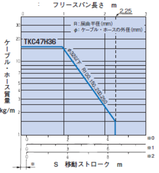
使用条件
移動ストローク:3m
ケーブル・ホース質量:4kg/m
ケーブル・ホース外径:Φ20mm(1本)
ケーブル・ホース許容屈曲半径:160mm
左表の横軸3mと縦軸4kg/mの交点を見い出し、この点を満足させるTKC47H36を選定します。
ケーブル・ホースの許容屈曲半径(r) < ケーブルベヤの屈曲半径(R)
この条件を満たすR=200 が決まります。
よって、上記条件より、TKC47H36W80R200となります。
速度・加速度確認
各品種および設置方法毎の移動速度の許容値を下記に示します。使用条件が、許容値を超えていないことを確認ください。(万一超えている場合は、当社までご相談ください)
| TKP | TKC | TKMK/ TKMT |
TKR | TKQ | TK | TKH | TKS | TKI | TKV | |
|---|---|---|---|---|---|---|---|---|---|---|
| 標準 | 300 | 300 | 300 | 300 | 600 | 60 | 60 | 60 | 120 | 150 |
| 支持ローラ | 150 | 150 | 150 | 150 | 150 | 60 | 60 | 60 | - | - |
| 支持プレート | - | 60 | - | - | - | - | - | - | - | - |
| 水平 | 60 | 60 | 60 | - | - | 30 | 30 | 30 | - | - |
| U字 | 300 | 300 | 300 | 300 | 600 | 60 | 60 | - | - | - |
| 逆U字 | 300 | 300 | 300 | 300 | 600 | 60 | 60 | - | - | - |
| 下側移動 | 300 | 300 | 300 | 300 | 600 | 60 | 60 | 60 | - | - |
| コンビネーション | 300 | 300 | 300 | 300 | 600 | 60 | 60 | 60 | - | - |
| ロングスパン仕様 | * | * | * | - | - | - | - | - | - | - |
| 走行ローラ | - | - | - | - | - | 30 | - | - | - | - |
| 縦旋回 | 60 | - | - | - | - | 60 | - | - | - | - |
| 水平旋回 | 30 | 30 | - | - | - | 30 | - | - | - | - |
※ロングスパン仕様(*印)はカタログを参照ください。
※-は適用外です。
※TKUA形に関しては当社までお問合せください。
| TKP | 2G |
|---|---|
| TKC | 3G |
| TKR | 2G |
| TKQ | 4G |
| TK | 1m/sec2 |
| TKS | 1m/sec2 |
| TKH | 1m/sec2 |
| TKI,TKV | 3G |
| TKMK,TKMT | ご相談ください |
加速度が非常に大きい場合は、非常に短時間で寿命となるおそれがあります。使用条件が、上表を超えていない事を確認ください。(万一、超えている場合は当社までご相談ください)
-参考- TKMK形、TKMT形 屈曲半径、断面寸法比較
オープンシリーズとクローズシリーズで屈曲半径と内幅寸法が異なるものがありますので下表をご参照ください。
| サイズ | 屈曲半径 | 内幅寸法 | 内高さ寸法 |
|---|---|---|---|
| TKMK47H28 | 55, 75, 100, 160, 200, 250 | 24, 56, - , 104, 152, 192 | 28 |
| TKMT47H26 | - , 75, 100, 160, 200, 250 | - , 56, 80, 104, 152, 192 | 26 |
| TKMK65H42 | 75, 95, 115, 145, 220, 300 | 66, 106, - , 154, 194, 258 | 42 |
| TKMT65H38 | - , 95, 115, 145, 220, 300 | 66, 106, 130, - , 194, 258 | 38.5 |
| TKMK95H58 | 140, 170, 200, 290, 380 | 114, - , 162, 210, 258, 306, 402, 514 | 58 |
| TKMT95H54 (プラカバータイプ) | 140, 170, 200, 290, 380 | 114, 130, 162, - , 258, 306 | 54.5 |
| TKMT95H54 (アルミカバータイプ) | 140, 170, 200, 290, 380 | 100~400(1mm毎) | 54.5 |
| TKMK125H72 | 180, 220, 260, 340, 380, 500 | - , 151, - , 247, 359, 407, 455, 503 | 72 |
| TKMT125H68 | - , 220, 260, 340, 380, 500 | 135, - , 183, 247 | 68.5 |
