技術資料 ドライブスプロケット
各部名称と寸法一般式
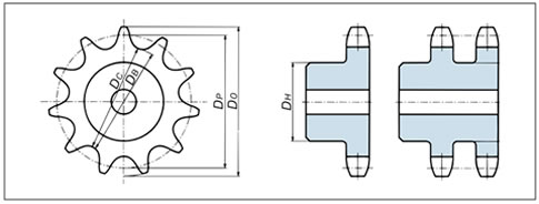
- DP = ピッチ円直径
- DO = 標準外径
- DB = 歯底円直径
- DC = 歯底距離
- DH = 最大ハブ径および最大溝径
- P = チェーンピッチ
- dl = ローラ外径
- N = 歯数
- DP = P/sin 180°N
- DO = P (0.6 + cot 180°N)
- DB = DP - dl
- DC = DB [偶数歯の場合]
- DC = DP cos 90°N - dl [奇数歯の場合]
- DH = P (cot 180°N - 1) - 0.76
歯形部仕様
1. 歯形
当社のスプロケット歯形には、JIS規格のS歯形を採用して機械歯切を行っています。
一部にJIS規格のU歯形も併用しています。

S歯形

U歯形
- pa = p(1 + DS - dlDP)
- DS = 2R = 1.005dl + 0.076
- U = 0.07(p - dl) + 0.051
- R = DS/2 = 0.5025dl + 0.038
- A = 35° + 60°/N
- B = 18° - 56°/N
- ac = 0.8dl
- Q = 0.8dl cos(35° + 60°/N)
- T = 0.8dl sin(35° + 60°/N)
- E = cy = 1.3025dl + 0.038
- xy = (2.605dl + 0.076) sin(9° - 28°/N)
- yz = dl[1.4 sin (17° - 64°/N) - 0.8 sin(18° - 56°/N)]
- G = ab = 1.4dl
[点bは線XY上のa点から線XYと180°/Nの角をなす線上にあります。] - K = 1.4dl cos180°/N
- V = 1.4dl sin180°/N
- F = dl [0.8 cos (18° - 56°/N)+ 1.4 cos(17° - 64°/N) - 1.3025] - 0.038
-
[S歯形はU = 0としたものです。]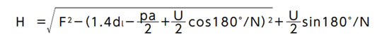
- S = pa2 cos180°/N + H sin180°/N
- 歯先が尖がる時の外径 = pa cot180°/N + 2H
- 最大圧力角 = x ab = 35° - 120°/N
- 最小圧力角 = x ab - B = 17° - 64°/N
- 平均圧力角 = 26° - 92°/N
N = 歯数、dl = ローラ外径、DP = ピッチ円直径、p = チェーンピッチ、pa =歯形ピッチ(S歯形のa - a1、U歯形のe - e1)
2. 歯部・横幅寸法
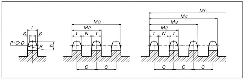
| サイズ | 各列 | t (最大) | C 2列 以上 |
2列・3列 | 4列以上 | |||||||||||
|---|---|---|---|---|---|---|---|---|---|---|---|---|---|---|---|---|
| g (参考) |
h | R (最小) |
1列 | 2列・3列 | 4列以上 | M2 | M3 | N | M2 | M3 | M4 | M5 | M6 | N | ||
| RS11 | 0.5 | 1.9 | 4.0 | 1.6 | - | - | - | - | - | - | - | - | - | - | - | - |
| RS15 | 0.6 | 2.4 | 5.1 | 2.0 | - | - | - | - | - | - | - | - | - | - | - | - |
| RS25 | 0.8 | 3.2 | 6.8 | 2.9 | 2.8 | 2.8 | 6.4 | 9.2 | 15.6 | 3.6 | 9.2 | 15.6 | 22.0 | 28.4 | 34.8 | 3.6 |
| RS35 | 1.2 | 4.8 | 10.1 | 4.4 | 4.3 | 4.2 | 10.1 | 14.4 | 24.5 | 5.8 | 14.3 | 24.4 | 34.5 | 44.6 | 54.7 | 5.9 |
| RS41 | 1.6 | 6.4 | 13.5 | 5.8 | - | - | - | - | - | - | - | - | - | - | - | - |
| RS40 | 1.6 | 6.4 | 13.5 | 7.3 | 7.1 | 7.0 | 14.4 | 21.5 | 35.9 | 7.3 | 21.4 | 35.8 | 50.2 | 64.6 | 79.0 | 7.4 |
| RS50 | 2 | 7.9 | 16.9 | 8.9 | 8.7 | 8.6 | 18.1 | 26.8 | 44.9 | 9.4 | 26.7 | 44.8 | 62.9 | 81.0 | 99.1 | 9.5 |
| RS60 | 2.4 | 9.5 | 20.3 | 11.9 | 11.7 | 11.4 | 22.8 | 34.5 | 57.3 | 11.1 | 34.2 | 57.0 | 79.8 | 102.6 | 125.4 | 11.4 |
| RS80 | 3.2 | 12.7 | 27.0 | 15.0 | 14.6 | 14.3 | 29.3 | 43.9 | 73.2 | 14.7 | 43.6 | 72.9 | 102.2 | 131.5 | 160.8 | 15.0 |
| RS100 | 4 | 15.9 | 33.8 | 18.0 | 17.6 | 17.2 | 35.8 | 53.4 | 89.2 | 18.2 | 53.0 | 88.8 | 124.6 | 160.4 | 196.2 | 18.6 |
| RS120 | 4.7 | 19 | 40.5 | 24.0 | 23.5 | 23.0 | 45.4 | 68.9 | 114.3 | 21.9 | 68.4 | 113.8 | 159.2 | 204.6 | 250.0 | 22.4 |
| RS140 | 5.5 | 22.2 | 47.3 | 24.0 | 23.5 | 23.0 | 48.9 | 72.4 | 121.3 | 25.4 | 71.9 | 120.8 | 169.7 | 218.6 | 267.5 | 25.9 |
| RS160 | 6.3 | 25.4 | 54.0 | 30.0 | 29.3 | 28.7 | 58.5 | 87.8 | 146.3 | 29.2 | 87.2 | 145.7 | 204.2 | 262.7 | 321.2 | 29.8 |
| RS180 | 7.1 | 28.6 | 60.8 | 33.7 | 33.0 | 32.3 | 65.8 | 98.8 | 164.6 | 32.8 | 98.1 | 163.9 | 229.7 | 295.5 | 361.3 | 33.5 |
| RS200 | 8 | 31.8 | 67.5 | 36.0 | 35.2 | 34.4 | 71.6 | 106.8 | 178.4 | 36.4 | 106.0 | 177.6 | 249.2 | 320.8 | 392.4 | 37.2 |
| RS240 | 9.5 | 38.1 | 81.0 | 45.0 | 44.0 | 43.1 | 87.8 | 131.8 | 219.6 | 43.8 | 130.9 | 218.7 | 306.5 | 394.3 | 482.1 | 44.7 |
スプロケットの最大ハブ径と一般的な最大軸穴径
| サイズ | RS25 | RS35 | RS40・41 | RS50 | RS60 | RS80 | RS100 | RS120 | RS140 | RS160 | RS180 | RS200 | RS240 | |||||||||||||
|---|---|---|---|---|---|---|---|---|---|---|---|---|---|---|---|---|---|---|---|---|---|---|---|---|---|---|
| チェーン ピッチ |
6.35 | 9.525 | 12.70 | 15.875 | 19.05 | 25.40 | 31.75 | 38.10 | 44.45 | 50.80 | 57.15 | 63.50 | 76.20 | |||||||||||||
| 歯数 | ハブ 径 |
最大 軸穴 径 |
ハブ 径 |
最大 軸穴 径 |
ハブ 径 |
最大 軸穴 径 |
ハブ 径 |
最大 軸穴 径 |
ハブ 径 |
最大 軸穴 径 |
ハブ 径 |
最大 軸穴 径 |
ハブ 径 |
最大 軸穴 径 |
ハブ 径 |
最大 軸穴 径 |
ハブ 径 |
最大 軸穴 径 |
ハブ 径 |
最大 軸穴 径 |
ハブ 径 |
最大 軸穴 径 |
ハブ 径 |
最大 軸穴 径 |
ハブ 径 |
最大 軸穴 径 |
| 10 | 13 | 3.2 | 19 | 8.8 | 26 | 14 | 32 | 18 | 39 | 22 | 52 | 32 | 65 | 42 | 78 | 50 | 92 | 60 | 105 | 70 | 118 | 78 | 131 | 88 | 158 | 108 |
| 11 | 15 | 5.6 | 22 | 11 | 30 | 18 | 37 | 22 | 45 | 27 | 60 | 38 | 76 | 50 | 91 | 60 | 106 | 71 | 121 | 80 | 137 | 92 | 152 | 103 | 183 | 126 |
| 12 | 17 | 7.2 | 25 | 13 | 34 | 20 | 43 | 26 | 51 | 31 | 69 | 45 | 86 | 57 | 103 | 69 | 121 | 80 | 138 | 93 | 155 | 106 | 173 | 118 | 207 | 144 |
| 13 | 19 | 8.8 | 28 | 15 | 38 | 22 | 48 | 30 | 57 | 36 | 77 | 51 | 96 | 64 | 116 | 79 | 135 | 91 | 155 | 105 | 174 | 119 | 193 | 132 | 232 | 162 |
| 14 | 21 | 10 | 31 | 17 | 42 | 26 | 53 | 33 | 64 | 41 | 85 | 57 | 107 | 72 | 128 | 85 | 150 | 101 | 171 | 117 | 192 | 132 | 214 | 148 | 257 | 180 |
| 15 | 23 | 12 | 35 | 20 | 46 | 28 | 58 | 37 | 70 | 46 | 93 | 61 | 117 | 80 | 140 | 95 | 164 | 111 | 187 | 129 | 211 | 146 | 235 | 163 | 282 | 199 |
| 16 | 25 | 13 | 38 | 21 | 50 | 31 | 63 | 41 | 76 | 51 | 102 | 68 | 127 | 85 | 153 | 104 | 178 | 122 | 204 | 141 | 229 | 159 | 255 | 179 | 306 | 216 |
| 17 | 27 | 14 | 41 | 24 | 54 | 34 | 68 | 45 | 82 | 53 | 110 | 74 | 137 | 93 | 165 | 112 | 193 | 132 | 220 | 152 | 248 | 173 | 275 | 193 | 331 | 232 |
| 18 | 29 | 16 | 44 | 26 | 59 | 37 | 73 | 49 | 88 | 59 | 118 | 80 | 148 | 100 | 177 | 121 | 207 | 144 | 237 | 165 | 266 | 186 | 296 | 208 | 355 | 252 |
| 19 | 31 | 17 | 47 | 29 | 63 | 41 | 79 | 51 | 94 | 62 | 126 | 84 | 158 | 108 | 189 | 129 | 221 | 153 | 253 | 177 | 284 | 199 | 316 | 224 | 380 | 268 |
| 20 | 33 | 19 | 50 | 30 | 67 | 44 | 84 | 55 | 100 | 66 | 134 | 90 | 168 | 114 | 202 | 140 | 235 | 163 | 269 | 188 | 303 | 213 | 337 | 238 | 404 | 283 |
| 21 | 35 | 20 | 53 | 33 | 71 | 47 | 89 | 59 | 107 | 72 | 142 | 95 | 178 | 122 | 214 | 148 | 250 | 175 | 285 | 200 | 321 | 226 | 357 | 254 | 429 | 303 |
| 22 | 37 | 21 | 56 | 35 | 75 | 50 | 94 | 62 | 113 | 77 | 150 | 101 | 188 | 128 | 226 | 157 | 264 | 185 | 302 | 212 | 339 | 239 | 377 | 266 | 453 | 318 |
| 23 | 39 | 22 | 59 | 37 | 79 | 51 | 99 | 65 | 119 | 80 | 159 | 109 | 199 | 137 | 238 | 165 | 278 | 196 | 318 | 224 | 358 | 254 | 398 | 278 | 477 | 338 |
| 24 | 41 | 24 | 62 | 40 | 83 | 54 | 104 | 70 | 125 | 83 | 167 | 113 | 209 | 144 | 251 | 176 | 292 | 205 | 334 | 235 | 376 | 265 | 418 | 294 | 502 | 354 |
| 25 | 43 | 25 | 65 | 42 | 87 | 57 | 109 | 73 | 131 | 88 | 175 | 120 | 219 | 152 | 263 | 184 | 307 | 217 | 351 | 249 | 394 | 275 | 438 | 310 | 526 | 372 |
注)最大軸穴径の決定は、使用条件に応じハブの肉厚を一般機械設計により決定してください。
参考までに一般的な場合(スプロケット材質SS400、JISキー溝)の基準的な最大軸穴径を示しています。なお、本表はJISのハブ直径計算式により求めたものです。
