技術資料 大形コンベヤチェーンスプロケット スプロケットの構造
1. 基本構造
歯形部には最適な高周波焼入れ硬化処理を施し、スプロケットの耐摩耗性および伝達能力の向上が図れます。
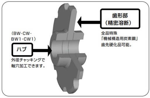
2. ハブ形式
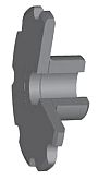
BW形
スプロケット歯形部の片側にハブを溶接した形式です。
適用
- RF10サイズ以下
- RF205サイズ以下

BW1形
スプロケット歯形部にハブを貫通させ片ハブ形として両側から溶接した形式です。
適用
- RF12サイズ以上
- RF6205サイズ以上

CW形
スプロケット歯形部の両側にハブを溶接した形式です。
適用
- RF10サイズ以下
- RF205サイズ以下
CW1形
スプロケット歯形部にハブを貫通させ両ハブ形として両側から溶接した形式です。
適用
- RF12サイズ以上
- RF6205サイズ以上
3. 歯形部形式
1. 形状
S1:歯先が円弧
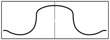
S2:歯先がフラット(斜線部がカットされた形状です)
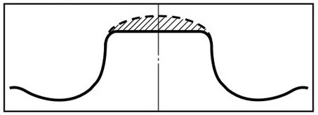
注)S2歯形について、Kアタッチメント付チェーンを使用時にS1歯形ではスラットなどとスプロケット外径が干渉するおそれのある品種に採用しています。特形チェーンやトップローラ付チェーンなどをご採用の際にはご相談ください。
2. 仕様
- ・普通仕様(記号N)
歯先硬化なし仕様で軽負荷、低摩耗雰囲気の用途に適します。 - ・歯先硬化仕様(記号Q)
歯先硬化処理を行った仕様です。耐摩耗性が要求される場合や高負荷条件での用途に適します。普通仕様(N)と歯先硬化仕様(Q)の使用区分は次表にしたがってください。
普通仕様と歯先硬化仕様の区分
| チェーン仕様 | ローラ形式 | 駆動側 | 従動側 | ||
|---|---|---|---|---|---|
| 普通雰囲気 | 摩耗雰囲気 | 普通雰囲気 | 摩耗雰囲気 | ||
| DT仕様 DTA仕様 |
S | Q | Q | N | Q |
| R | N | Q | N | N | |
| F | N | Q | N | N | |
| AT仕様 ATA仕様 |
S | Q | Q | N | Q |
| R | Q | Q | N | Q | |
| F | Q | Q | N | Q | |
上記は一般的な使用条件を設定した使用区分です。特に厳しい摩耗雰囲気、高荷重条件での使用条件の場合は当社にお問合せください。
4. 軸穴仕上追加工仕様
面倒な穴加工を短納期で完成できるように軸穴寸法を下記仕様で加工します。なお、止めねじは付属していません。
標準軸穴加工仕様
| 軸穴公差 | キー溝幅公差 | タップ加工 |
|---|---|---|
| H8 | JIS B1301-1996 普通形 Js9 |
キー上と120°間隔の 2ヵ所にタップ加工 |
| 旧JIS B1301-1959 2種 E9 |
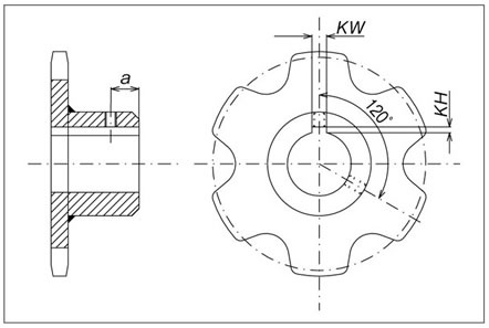
キー溝と歯先の位相
キー溝はスプロケット歯先中心とキー溝中心を合わせるように加工しています。チェーンを並列でご使用される場合は当社へお問い合わせください。
キー溝とタップの仕様・寸法
| JIS普通形キー キー溝幅公差 Js9 | |||
|---|---|---|---|
| 適用軸穴径 | キー溝幅 KW |
キー溝深さ KH |
タップサイズ MX |
| 22をこえ30以下 | 8 | 3.3 | M6 |
| 30をこえ38以下 | 10 | 3.3 | M8 |
| 38をこえ44以下 | 12 | 3.3 | |
| 44をこえ50以下 | 14 | 3.8 | |
| 50をこえ58以下 | 16 | 4.3 | M10 |
| 58をこえ65以下 | 18 | 4.4 | |
| 65をこえ75以下 | 20 | 4.9 | M12 |
| 75をこえ85以下 | 22 | 5.4 | |
| 85をこえ95以下 | 25 | 5.4 | M16 |
| 95をこえ110以下 | 28 | 6.4 | |
| 110をこえ130以下 | 32 | 7.4 | M20 |
| 130をこえ150以下 | 36 | 8.4 | |
| 150をこえ170以下 | 40 | 9.4 | |
| 170をこえ200以下 | 45 | 10.4 | M24 |
| 200をこえ230以下 | 50 | 11.4 | |
| 旧JIS2種キー キー溝幅公差 E9 | |||
|---|---|---|---|
| 適用軸穴径 | キー溝幅 KW |
キー溝深さ KH |
タップサイズ MX |
| 20をこえ30以下 | 7 | 3 | M6 |
| 30をこえ40以下 | 10 | 3.5 | |
| 40をこえ50以下 | 12 | 3.5 | M8 |
| 50をこえ60以下 | 15 | 5 | |
| 60をこえ70以下 | 18 | 6 | M10 |
| 70をこえ80以下 | 20 | 6 | M12 |
| 80をこえ95以下 | 24 | 8 | |
| 95をこえ110以下 | 28 | 9 | M16 |
| 110をこえ125以下 | 32 | 10 | M20 |
| 125をこえ140以下 | 35 | 11 | |
| 140をこえ160以下 | 38 | 12 | |
| 160をこえ180以下 | 42 | 13 | |
| 180をこえ200以下 | 45 | 14 | M24 |
| 200をこえ224以下 | 50 | 15.5 | |
| 224をこえ250以下 | 56 | 17.5 | |
上記以外の加工仕様のときは下記内容をお知らせください。
- ・軸穴形状・寸法径・公差
- ・キー溝品種・寸法・公差
- ・タップサイズと位置
