技術資料 直動機器 ジップチェーンアクチュエータ 取扱
取扱
据付時の注意事項
- 1. 潤滑にグリースを使用しますので、グリースが飛散することがあります。周囲の影響に充分ご注意ください。 (飛散を懸念される場合はジャバラを推奨いたします。) 特に吊下でご使用になる場合はグリースが垂れる可能性があります。
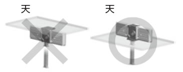
- 2. 押上、水平および吊下方向に取付ができます。ただし、水平および吊下方向に取付ける場合、本体自重および搬送物の重さ(力)が取付けボルト自体に加わる状態で使用すると機器を破損する恐れがあります。取付ボルトで荷重を受けない設置方法にしてください。(図1)
吊下取付
水平取付 押出時
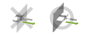
水平取付 引張時
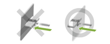
図1 据付方向の可否(一例)
- 3. モータ無の場合、モータ、減速機、本体などの据付けに当たっては、適正な据付が行えるよう剛性が高く、最大荷重が加わっても、据付け時の心出し精度が狂わない安全率を見込んだ強固な架台を用意してください。また、モータ出力軸とZCA入力軸心高さを合わせる機構を別途設けてください。軸心高さがずれている場合、モータ出力軸およびZCA入力軸に回転曲げの力が作用し、軸部破損の要因となります。
- 4. 軸をチェーン・ベルトなどで駆動する場合、軸に作用するオーバハングロードが許容オーバハングロード以下になることをご確認ください。 (詳細は選定頁をご参照ください)
- 5. 取付は駆動部および先端金具にある各4ヵ所の取付用タップを利用して、確実に固定してください。
(取付ボルトは付属していません。)
取付用ボルトサイズは表1に従い、ボルトの強度区分は10.9(JISB1051)以上のものを使用ください。取付部材強度に見合ったボルトねじこみ深さを考慮ください。
表1 取付ボルトサイズ
形番 駆動部(底面) 駆動部(側面) 先端金具 ZCA25 M5 M5 M4 ZCA35 M6 M6 M5 ZCA45 M8 M8 M8 なお、取付時には、ボルト緩み止めを施してください。
- 6. いかなる場合もストロークエンドでの当て止めは行わないでください。当て止めを行いますと本体内部に重大な損傷をあたえます。
- 7. 本体に加わる荷重はジップチェーンの進行方向と同軸上に作用するようにしてください。作用方向や位置が不適切ですとジップチェーンに曲げ荷重や横荷重が加わり破損のおそれがあります。
(図2)
必ず進行方向に直線ガイドなどを設けてジップチェーンが直接横荷重や曲げ・ねじれモーメントを受けないようにご使用ください。
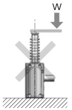
図2
- 8.ジップチェーンはリンクを多数噛合わせることで柱状になります。柱状になったチェーンでは、多少のねじれやそりが生じる場合があります。
- 9. 使用ストロークに対して、ストロークは余裕を見込んでご使用ください。ストローク範囲を超えると、ストッパの破損やチェーンが抜けたり、先端金具が駆動部と衝突し本体が破損する恐れがあります。
- 10. ストロークを規制するために設置するリミットスイッチは、惰行量を見込んで設定ください。
- 11. 軸の回転方向とジップチェーンの進行方向は事前に確認してください。 (外形寸法図をご参照ください) 回転方向を間違うと本体が破損するおそれがあります。モータ付の場合、速度により電気配線に対するチェーンの進行方向が異なりますのでご注意ください。
- 12. ジップチェーン、駆動部開口部などには、粉塵や切粉などの異物が絶対に付着もしくは混入しないようにしてください。これらは摩耗を促進し、チェーンの破断や可動部破損などの大きな原因に繋がります。
- 13. 駆動部底面を下向きに据付けた場合、ストローク下限で軸のキー溝がほぼ上面(図3参照)を向きます。ただし同期等を行う場合、バックラッシなどで個体差があるため、多少のずれが生じますので位相を調整する機構を別途設けてください。位相がずれている場合は、ZCA1台あたりにかかる負荷が大きくなり、チェーンの座屈、軸破損等の原因となります。位相を合わせる際は、つばきパワーロック®等をご使用頂き、ジップチェーン下限位置で先端高さを合わせてください。
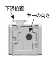
図3
- 14.吊下装置に使用される場合は、万一チェーンが切断した場合に備えて安全装置や安全柵を必ず設け吊下物の下へは絶対に入らないでください。 人身事故に繋がる危険性がある場合には製造および販売いたしかねます。
- 15. 押上、吊下取付用のジャバラを水平取付でご使用になると早期にジャバラが破損します。水平取付の場合は特殊部品を組込んだ専用のジャバラが必要です。別途製作しますのでご用命ください。
- 16. 結露や湿気などにより、グリースが早期劣化、流出する可能性があります。特殊な環境でご使用の際は見積時にご相談ください。
- 17. ジップチェーンアクチュエータに追加工を行わないでください。
