技術資料 直動機器 パワーシリンダ 取扱
据付・保守:Tシリーズ
据付
据付方向
水平、垂直、傾斜など自由です。
据付環境
- ・全機種とも通常の屋外で使用できる全閉構造となっていますが、常時水や蒸気などのかかるような悪環境下や雪が積もるような場所は、屋外形といえども適当なカバーが必要です。周囲温度はご使用条件にもよりますが、通常-15~40℃の範囲内でご使用になれます。40℃以上でご使用になる場合は、必ず断熱カバーなどで保護してください。引火性雰囲気では、絶対使用しないでください。爆発・火災発生のおそれがあります。また、1Gを越える振動や衝撃がかかる場所でのご使用は避けてください。
- ・屋外でキャブタイヤケーブル・リード線付仕様をご使用時には防水処理を十分に行ってください。
据付方法
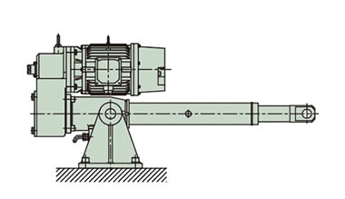
- ・本体の据付は、トラニオンマウントまたはクレビスマウントで使用してください。先端部は、U形またはI形先端金具にて取付けてください。
- ・トラニオン取付けの場合、トラニオンピンおよびトラニオン穴部にグリースを塗ってください。先端金具の連結ピンおよびクレビス取付け時の連結ピンにもグリースを塗ってください。
- ・シリンダが作動することにより本体が大きく揺動する場合は、連結部に滑り軸受けや転がり軸受けを使うようにご配慮ください。
なお、トラニオン穴に滑り軸受を装着したものをご要望の場合は当社までご相談ください。 - ・トラニオンピンまたはクレビスおよび先端金具の連結ピンが鉛直方向を向く場合(シリンダを横に寝かせた場合)でかつ本体が揺動する場合は、トラニオン穴部もしくはクレビス金具、先端金具の側面部に滑り軸受け材を挿入するなど摩耗対策をとってください。
図1 据付方法
トラニオンマウント
クレビスマウント

※マウント用金具はオプションの項をご参照ください。
手動操作
手動でストロークを調整する場合は、ブレーキ付モータのブレーキ解放を行った後、減速部の手動ハンドル軸をモンキーレンチやソケットレンチで回してください。
| 警告 |
ロッド部に荷重が作用している時は、ブレーキ解放前に荷重を取除いてください。 |
|---|
手動軸1回転当りのロッドの移動量は標準機種一覧(こちら)をご参照ください。
ロッドの回転防止
- 1.ロッドには推力に伴って回転力(こちら参照)が生じますので回転防止が必要です。定格推力時のロッド回転力は機種一覧に記載しています。一般にはロッド先端部を被動機に取付けることによって回転防止が可能になる場合がほとんどです。
- 2.先端部をフリーにして動かす場合や滑車をつけロープなどを引張る用途の場合は通常ロッド回転防止が必要です。パワーシリンダに回り止め仕様がご要望の場合は当社までご相談ください。なお、外部リミットスイッチユニットのLSロッドは回転防止には使えません。
ロッドの横荷重
ロッドに曲げ荷重(横荷重)が作用しないよう据付けてください。
ロッドに対し直角方向の荷重(横荷重)や荷重方向が偏心した荷重(偏心荷重)がかかる場合は下記のような対策を取ってください。
(1)横荷重…ロッド部にガイドローラ等を設ける。(図3)
図3 横荷重
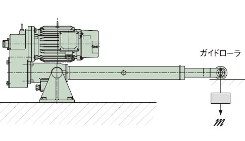
ロッドに直接横荷重がかかるのは避けガイドローラなどを設けてください。
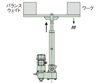
(2)偏心荷重…バランスウエイト等を設ける。(図4)
図4 偏心荷重
偏心荷重がかかる場合はバランスウエイト等を設けてください。
※このレイアウトでは、別途ガイドが必要です。
メガテストについて
本シリンダは内蔵の電源モジュールを破損することがありますので、メガテストは厳禁です。ただし、外部回路のメガテストを行う場合、端子箱のブレーキ配線を外してください。
ストローク調整外部LS(オプション)の設定
- ・パワーシリンダ本体にはリミットスイッチを取付けるタイプのオプションが選択できますので、ご利用ください。
- ・ストロークの両エンドの規制は、リミットスイッチにて行ってください。
- ・ストローク範囲内でご使用ください。 ストロークがオーバすると破損するおそれがあります。
- ・リミットスイッチの調整は惰行距離(こちら)を見込んで設定ください。
- ・称呼ストローク100%でご使用の時は寸法表のXA寸法以内でシリンダが停止するようリミットスイッチを設定ください。
- ・2台以上のパワーシリンダを同時に運転する場合は、各シリンダにリミットスイッチを上限、下限に取付けてください。
- ・Cタイプの推力検知用リミットスイッチの調整をお客様では絶対行わないでください。 推力検知の設定値が大きく異なるおそれがあります。
- ・パワーシリンダTシリーズの高速タイプ(H速度)のものは、惰行距離が長いためリミットスイッチをストライカが乗り越えてしまう可能性があります。このため制御回路上でリミット信号は必ず自己保持をとって運用ください。
- ・ストローク調整外部LS(オプション)縦取付(ストローク300mm以下)...外部LSのコネクタ部がトラニオン取付ベース面より下に出ます。(図5)
図5 ストローク調整外部LS(オプション)縦取付
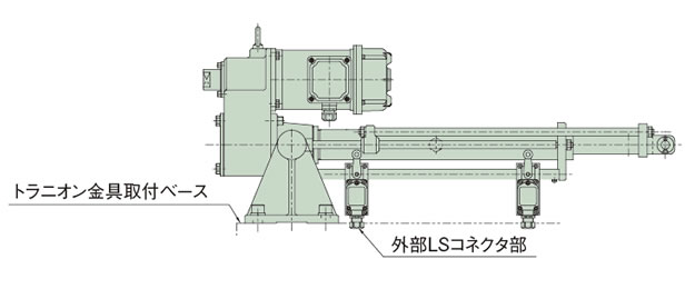
ケーブル配線を必要としますので、取付ベースにご配慮ください。
保守
ボールネジの給脂
ボールネジはグリース潤滑であらかじめ塗布していますのでそのまま使用してください。グリースの補給は表1・2を目安にしてください。ボールネジの給脂は、外筒部の給脂口ボルトを外しロッドをフルストローク前進させ、グリースガンでネジ外周に塗布し、ご使用ストロークの範囲を往復させてください。この動作を2~3回繰り返してください。
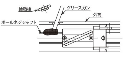
給脂1回の総塗布量はストローク100mm当たり10~15g程度(T250~T4000)です。
| 警告 |
給脂口には絶対指を入れないでください。 |
|---|
表1 推奨グリース(必ずEP(極圧)グリースをご使用ください。)
| 使用区分 | 会社名 | グリース名称 |
|---|---|---|
| ボールネジ | (株)椿本チエイン | JWGS100G |
| 出光興産(株) | ダフニーエポネックス SR No.2 ※1 | |
| 日本グリース(株) | ニグルーブ EP-2K | |
| エクソンモービル・ジャパン(同) | モービラックス EPNo.2 | |
| コスモ石油ルブリカンツ(株) | コスモグリースNEWダイナマックス EPNo.2 | |
| シェルルブリカンツジャパン(株) | シェル ガダス S2 V220 J 2 (EP) ※2 |
※1出荷時の封入グリースです。
※2旧名称:シェルアルバニヤ EP グリース2
注)JWGS100Gは、100g容器で別売しています。(こちらをご参照ください。)
*上記に記載の商品名は各社の商標または登録商標です。
リニパワージャッキやパワーシリンダのメンテナンスに最適!
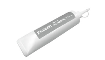 (100g入)
形番:JWGS100G
表2 給脂サイクル
| 使用頻度 | 給脂サイクル |
|---|---|
| 1001往復/日以上~ | 1ヵ月~3ヵ月毎 |
| 501~1000往復/日 | 3ヵ月~6ヵ月毎 |
| 101~500往復/日 | 6ヵ月~1年毎 |
| ~100往復/日以下 | 1年~1.5年毎 |
※上表値は、より長く使用していただくための値であり、寿命を示す値ではありません。
減速部の給脂
減速部のギヤ、およびベアリングは、グリース潤滑であらかじめギヤケース中に充填していますので、特に給脂の必要はありません。
減速部初期封入グリース
- ギヤケース部:ダフニーエポネックスSR No.1
- 遊星減速部:モリギヤグリースNo.1
