技術資料 直動機器 パワーシリンダ 取扱
エコシリーズ・サーボタイプサーボモータ組付手順(お客様にてお取付けいただく場合)
モータ直結の場合
サーボモータをご用意ください。 (出力軸はキー溝なし、キー溝付でもご使用いただけます。)
モータフランジのカップリング取付穴が上面になるよう設置してください。 (□45・□105フレームのみ)
モータ軸の錆や埃、錆止め油などは、きれいにふき取ってください。
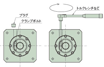
カップリングのクランプボルトを緩めてください。
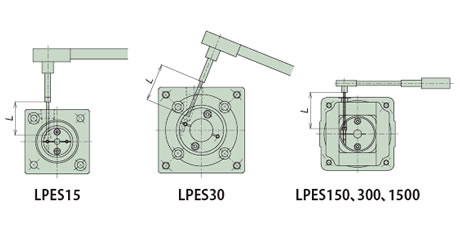
カップリングケースのプラグを外し、入力軸を回して、カップリングのクランプボルト頭をプラグ穴の位置に合わせます。
*LPES30は下図のように、斜めにトルクレンチを差込む必要があります。
モータ軸をカップリングにスムーズに挿入してください。
*モータを回転方向に回すとクランプボルトとの位相がズレることがあります。
モータ軸を傾けて挿入しないように十分に注意してください。
インロ部を完全に挿入後、モータ取付ボルトにて取付けてください。
トルクレンチを用いて、カップリングのクランプボルトを指定の締付トルクで締付けてください。
取外しておいたプラグをカップリングケースに取付けてください。
※詳細は取扱説明書をご参照ください。
| 形番 | カップリング ボルトサイズ |
締付トルク N・m{kgf・m} |
L寸法 mm |
|---|---|---|---|
| LPES15 | M2 | 0.5{0.04} | 30 |
| LPES30 | M2.5 | 1.0{0.10} | 40 |
| LPES150 | M4 | 3.8{0.39} | 60 |
| LPES300 | 70 | ||
| LPES1500 | M6 | 12{1.22} | 90 |
精密遊星減速機付の場合
1. モータ軸が丸軸の場合
モータ取付面が上部になるように減速機を設置してください。
モータ軸の錆や埃、錆止め油などは、きれいにふき取ってください。
アダプタ部のプラグを外し、入力軸を回して、ボルトの頭をプラグ穴の位置に合わせます。
六角棒スパナなどによりセットボルトが緩んでいることを確認してください。
モータ軸を入力軸穴にスムーズに挿入してください。この時、モータ軸を傾けて挿入されますと軸穴とのカジリなどが生じ正しい取付けができなくなるので十分注意してください。
インロ部が完全に挿入された後、適切な締付トルクでモータをアダプタに完全に固定してください。
入力軸のセットボルトをトルクレンチなどにより下表の締付トルクで締付けてください。この時、規定の締付トルク以下で締付けられた場合、セットボルトの緩みによるモータ軸のスリップなど不具合につながりますので十分ご注意ください。セットボルトにはロックタイトなどの緩み止めを塗布しないでください。適正な締結トルクが得られず締結不足になる場合があります。
プラグを取付けてください。以上でモータのセットは完了です。
クランプボルトの締付け
予期せぬ衝撃が発生した場合、クランプかん合部がすべることが想定されます。昇降駆動等では別途安全機構をご配慮ください。
クランプボルト締付トルク表
| ボルトサイズ | M3 | M4 | M5 | M6 | M8 | M10 |
|---|---|---|---|---|---|---|
| 締付トルク N・m{kgf・m} |
1.9 {0.18} |
4.3 {0.44} |
8.7 {0.89} |
15 {1.50} |
36 {3.70} |
71 {7.20} |
*ボルトの締付トルクは上記の数値×1.0~1.2 の範囲にしてください。
モータ取付ボルト締付トルク表
| ボルトサイズ | M3 | M4 | M5 | M6 | M8 |
|---|---|---|---|---|---|
| 締付トルク N・m{kgf・m} |
1.1 {0.11} |
2.5 {0.26} |
5.1 {0.52} |
8.7 {0.89} |
21 {2.10} |
*ボルトの締付トルクは上記の数値×1.0~1.2 の範囲にしてください。
2. キー付モータの取付
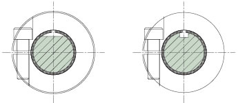
キー付きのモータ軸は、キーを取外せば丸軸と同様にクランプタイプでご使用いただけます。
モータ軸キー溝(Dカット)、各スリット、セットボルトは右図に示す位置にセットしてください。
その他は丸軸の場合と同様の手順で減速機に取付けてください。
選定時の注意事項(エコシリーズ・サーボタイプ)
- ・本シリンダは回り止め機構を設けていません。ロッドには推力に伴って回転力が生じますので、必ず相手装置側で回転防止を行ってください。
最大推力時のロッドに生じる回転力は下表の通りになります。形番 LPES15 LPES30 LPES150 LPES300 LPES1500 ロッド回転力
N・m{kgf・m}0.16{0.016} 0.32{0.031} 1.60{0.16} 3.19{0.33} 26.6{2.72} - ・本シリンダはシリンダ本体に荷重保持機構を設けていません。停止時および製品故障時に危険な状態が予想される場合には、荷重保持用として電磁ブレーキ付サーボモータを使用するか、外部にブレーキ機構を設けてください。昇降装置への使用または水平使用で位置ずれが問題になる場合も同様です。
- ・パワーシリンダは屋内形構造になっています。錆の発生などの問題がありますので屋内の環境の良い場所に保管してください。湿気には十分ご注意ください。急激な温度変化のある場所に設置しますと結露が生じ、故障や錆の原因になりますのでご注意ください。
- ・腐食性雰囲気の中での保管や使用はしないでください。また、引火性雰囲気での使用はできません。
- ・密閉した容器内など放熱が期待できない場所での使用は故障の原因となりますので使用しないでください。
据付時の注意事項(エコシリーズ・サーボタイプ)
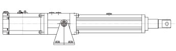
- ・本体の据付けはトラニオンマウントまたはフランジマウント(LPES150以下のみ可)にてご使用ください。
揺動を伴うご使用の場合には、I形先端金具またはU形先端金具をお選びください。横荷重が加わる場合は、ガイドを設けて直接横荷重や曲げモーメントを受けないようにしてください。 - ・トラニオンマウントで取付ける場合は水平および垂直取付け可能です。
- ・フランジマウントで取付ける場合は、垂直方向で取付けてください。(右図参照)
※LPES300以上のタイプでのフランジマウントの場合は当社へお問合せください。
※ジャバラ付の場合フランジ取付はできません。 - ・シリンダの揺動がなく静止させた状態でご使用の場合には(1)フランジマウント(2)トラニオンマウント+フートマウントをお選びください。水平および垂直取付けも可能です。(□45フレームのみ)
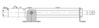
- ・長ストロークでかつ水平でご使用の場合、下図のように、別途フレーム先端下部を支持してください。
その際、フレームと支持ベースは固定しないでください。
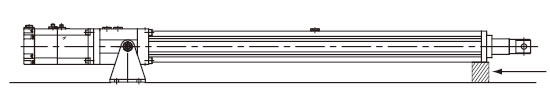
フレーム先端支持
(固定不可)
トラニオンマウント
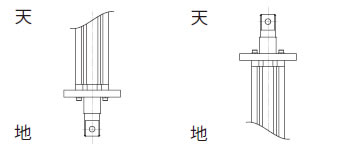
フランジマウント
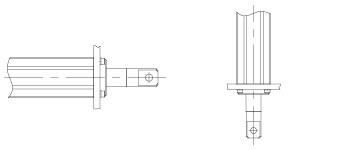
(1)フランジマウント
(2)トラニオンマウント+フートマウント
使用上の注意事項(エコシリーズ・サーボタイプ)
- ・本シリンダはシリンダ本体に過負荷保護機構を設けていませんので、サーボドライバ(サーボアンプ)の過負荷、過電流、過電圧に対する保護を行ってください。また、パワーシリンダの相手側装置はサーボモータの最大トルクに耐えうる強度で製作してください。
- ・本シリンダには構造上手動操作軸を設けていませんので、シリンダ位置の調整は微速にてサーボドライバ(サーボアンプ)操作でご対応ください。
- ・本シリンダのネジ軸には出荷時にダフニーエポネックスSRNo.2を塗布していますが、定期的な給脂が必要です。
グリースの給脂サイクルは右表をご参照ください。
グリースの塗布量はストローク100mm当り10~15gです。
なお、当社にてメンテナンス用グリースとして、JWGS100Gをご用意(別売)しています。
(こちらをご参照ください。)※ロッド外周面には、油膜が切れないように給脂サイクルに合わせてグリースを塗布してください。
グリースはネジと同一のものをご使用ください。※給脂サイクルについては、ご使用状況に応じて見極めをお願いします。
使用頻度 給脂サイクル 1001往復/日以上~ 1ヵ月~3ヵ月毎 501~1000往復/日 3ヵ月~6ヵ月毎 101~500往復/日 6ヵ月~1年毎 ~100往復/日以下 1年~1.5年毎
リニパワージャッキやパワーシリンダのメンテナンスに最適!
(100g入)
形番:JWGS100G
