技術資料 直動機器 パワーシリンダ選定
選定:Tシリーズ・マルチ仕様
必要条件
使用機械と使用方法
推力または荷重 N{kgf}
ストローク mm
速度 mm/s
使用頻度 起動回数/min
使用時間 時/日と年間稼働日数 日/年
使用機械の負荷の性質
使用環境
選定手順
- 1.使用方法よりタイプ(B or C)を決めてください。
- 2.負荷の性質と使用機械により使用係数を求めます。
- 3.ストローク、使用頻度、使用時間から年間走行距離を求めます。
年間走行距離 km = 実ストローク m×使用頻度回/日×稼働日数/年×10-3
- 4.負荷がストローク途中にて大きく変動する場合には、次式にて等価荷重を算出してください。
PM = PMIN + 2×PMAX 3
PM:等価荷重N{kgf}
PMIN:最小荷重N{kgf}
PMAX:最大荷重N{kgf}
- 5.装置最大荷重に使用係数を乗じ、連動運転の場合には、連動係数と、連動台数で除して補正推力を求めてください。
補正推力 = 装置最大荷重×使用係数 連動台数×連動係数
- 6.補正推力とストロークをもとに標準機種から使用形番を選んでください。
- 7.荷重-期待走行距離より寿命を算出し、年間走行距離と比較し、寿命のチェックを行ってください。
使用係数
| 負荷の性質 | 使用機械例 | 使用係数 |
|---|---|---|
| 衝撃のない円滑な作動 慣性小 |
ダンパ、バルブの開閉 コンベヤ切替装置 |
1.0~1.3 |
| 軽い衝撃のある作動 慣性中 |
ホッパゲートの開閉、各種移載装置、 各種リフタ昇降 |
1.3~1.5 |
| 大きな衝撃、振動のある作動 慣性大 |
台車による重量物搬送、ベルトコンベヤ用 バッファ、大形蓋の反転開閉装置 |
1.5~3.0 |
注)上記使用係数は一般的な目安であり、使用条件を考慮して決定ください。
連動係数
| 連動台数(台) | 2 | 3 | 4 | 5 | 6 |
|---|---|---|---|---|---|
| 連動係数 | 1.0 | 1.0 | 1.0 | 0.8 | 0.67 |
注)連動台数は、最大6台までです。
荷重 - 期待走行距離
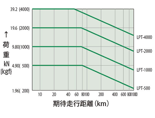
期待走行距離はL10※寿命より算出しています。
※L10寿命とは、一群の同一ボールネジを同一条件下で運転した場合に、全体の90%以上がハクリ(Flaking)を起こさず達し得る寿命のことです。
駆動源の選定:Tシリーズ・マルチ仕様
駆動用モータとして変減速機付モータ、DCモータ、サーボモータ、ポールチェンジモータなどが使用可能です。使用モータは、パワーシリンダが高効率のため、負荷荷重により逆転します。必ずブレーキ付のものをご使用ください。ブレーキはスプリングクローズ形のもの、ブレーキトルクは150%以上のものをご使用ください。
駆動用モータは、次式にてご選定ください。
必要入力トルクを算出の上、算出されたトルク値を満足するモータをご使用ください。
パワーシリンダの諸元につきましては、各製品の主要諸元ページをご参照ください。
T = W×ℓ 2×π×R×η×1000 + To
T:必要入力トルク N・m{kgf・m}
W:荷重(負荷) N{kgf}
ℓ:ネジリード mm
R:ギヤ速比 = 2
η:総合効率 = 0.855
To:無負荷空転トルク N・m{kgf・m}
注)必要以上に容量の大きいモータを使用しますと、ストローク途中にてロックした場合、モータの回転エネルギーにより衝撃荷重がパワーシリンダに作用し、破損の原因となるおそれがありますのでご注意ください。また、結線はブレーキ別切りとしてください。
選定時の注意事項:Tシリーズ・マルチ仕様
押付(引付)許容停止回数
高頻度で押付(引付)停止をする場合
1日10回以上の頻度でご使用になる場合には、下表の機種別基準総停止回数をご参照ください。
| タイプ | LPTC500 ~ LPTC4000 | ||
|---|---|---|---|
| 速度 (mm/s) |
LPTC500 | ~30 | ~60 |
| LPTC1000 | ~30 | ~60 | |
| LPTC2000 | ~30 | ~60 | |
| LPTC4000 | ~30 | ~42 | |
| 基準総停止回数 (×104回) |
30 | 10 | |
- 注)
1.押付(引付)停止でご使用になる場合にはブレーキ部の結線は別切りを推奨します。 - 2.上表を超えてご使用になる場合にはストローク調整LSによる停止をおすすめしますが、装置の都合上押付(引付)停止や、内部停止が必要な場合は当社にご相談ください。
- 3.押付(引付)停止でご使用になる場合、相手装置の強度は定格推力の250%以上としてください。
連動運転およびストローク位置制御をされる場合
停止中に負荷側から過負荷が作用した場合でもロッドが動いては困る場合
Cタイプの場合はバネ機構が作動部に内蔵されていますので負荷側から大きな荷重が作用した場合バネはたわみ、その分だけロッドは動くことになります。
負荷がなくなれば元の位置に復帰します。
- ・マルチ仕様のBタイプには過負荷保護機能が付いていません。シリンダ本体に過負荷保護機能が必要な場合はCタイプをお選びください。
- ・入力軸や出力軸にスプロケット・ギヤ・プーリなどを取付ける場合、軸に作用するオーバハングロードが許容オーバハングロード以下になることをご確認ください。
許容O.H.L. ≧ T×f×Lf R
OHL:オーバハングロード(N{kgf})
T:負荷トルク(N・m{kgf・m})
f:伝動要素係数
Lf:荷重の作動位置による係数
R:スプロケット、ギヤ、Vプーリなどのピッチ円半径(m)
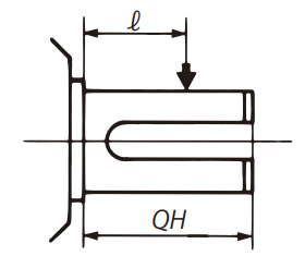
QH:軸の長さ
ℓ:荷重の作用位置
伝動要素係数(f)
| スプロケット | 1.00 |
|---|---|
| ギヤ | 1.25 |
| Vベルト | 1.50 |
| 平ベルト | 2.50 |
荷重の作用位置による係数(Lf)
| ℓ/QH | 0.25 | 0.38 | 0.5 | 0.75 | 1 |
|---|---|---|---|---|---|
| Lf | 0.8 | 0.9 | 1 | 1.5 | 2 |
図表1
| パワーシリンダ形番 | LPT500 | LPT1000 | LPT2000 | LPT4000 |
|---|---|---|---|---|
| 許容オーバハングロード N{kgf} | 803{82} | 1303{133} | 2251{230} | 4005{409} |
