技術資料 直動機器 リニパワージャッキ選定
必要条件
使用機械 ..... テーブルリフタ、舞台昇降装置、コンベヤライン切替装置etc
レイアウト ..... 連動パターン(4台、6台etc)、駆動、カップリングetc
最大荷重(W) ..... 負荷またはワークの質量 N{kgf}
ネジ軸速度(V) ..... ジャッキの必要速度 m/min
ストローク ..... 実際に使用するストローク mm
ネジタイプ ..... ボールネジタイプ(JWB)、ハイリードボールネジタイプ(JWH)、台形ネジタイプ(JWM)
取付形状 ..... 基本形仕様(押上用or吊下用、回り止め要or不要)、トラベリングナット仕様(押上用or吊下用)
据付状態 ..... ベース固定、軸端クレビスetc・圧縮荷重作用時は座屈検討
期待寿命 ..... ジャッキ耐用年数(JWB、JWHのみ)
選定手順
1. 補正荷重Wsの算出
負荷の性質を考慮し、使用係数(表1)を参照の上、補正荷重Wsを求めます。
補正荷重 Ws (N{kgf}) = 最大荷重 W (N{kgf})×使用係数 Sf
表1 使用係数 Sf
| 負荷の性質 | 使用例 | 使用係数 |
|---|---|---|
| 衝撃の無い円滑な作動 負荷慣性 小 |
バルブの開閉 コンベヤ切換装置 |
1.0~1.3 |
| 軽い衝撃のある作動 負荷慣性 中 |
各種移動装置 各種リフタ昇降 |
1.3~1.5 |
| 大きな衝撃、振動のある作動 負荷慣性 大 |
台車による物搬送、圧延ローラの位置決め保持 | 1.5~3.0 |
注)上記使用係数は一般的な目安であり、使用条件を考慮して決定ください。
2. ジャッキ1台当たりの荷重Wの算出
補正荷重Wsよりジャッキ1台当たりの荷重Wを求めます。連動運転の場合は連動係数(表2)を参照の上計算します。
ジャッキ1台当たりの荷重 W (N{kgf}) = 補正荷重 Ws (N{kgf}) ジャッキ使用台数×連動係数 fd
表2 連動係数 fd
| 連動台数(台) | 2 | 3 | 4 | 5~8 |
|---|---|---|---|---|
| 連動係数 | 0.95 | 0.9 | 0.85 | 0.8 |
3. リニパワージャッキの形番を仮選定
「仮選定のポイント」を参考にジャッキの形番を仮選定します。
仮選定のポイント
- 1.ウォーム速比はネジ軸速度より仮選定します。判断が難しい場合は速比Hで検討します。
- 2.ストロークは使用ストロークに余裕を見込んで選定します。
- 3.必要に応じてオプションを選定します。
4. 座屈・ネジ軸回転速度の確認
5. 必要入力回転速度の確認
必要ネジ軸速度よりジャッキの必要入力回転速度を求めます。
N = V ℓ ×R
N:入力回転速度 r/min
V:ネジ軸速度 m/min
ℓ:ネジリード m
R:ウォーム速比
6. 必要入力トルクの確認
必要入力トルクを計算します。
T = W×ℓ 2×π×R×η + To
T:必要入力トルク N・m{kgf・m}
W:昇降荷重 N{kgf}
ℓ:ネジリード m
π:円周率 3.14
R:ウォーム速比
η:ジャッキ総合効率
To:無負荷空転トルク N・m{kgf・m}
- 注)
ネジリード、ウォーム速比、総合効率、無負荷空転トルクは各製品の主要諸元ページをご参照ください。
ネジリードの単位にご注意ください。例) 8mm → 0.008m
7. 必要入力容量の確認
SI単位 P = T×N 9550
重力単位 P = T×N 974
T:必要入力トルク N・m{kgf・m}
P:必要入力容量 kW
N:入力回転速度 r/min
8. 許容オーバハングロードの検討
入力軸にスプロケット、ギヤ、ベルトなどを取付ける場合は、許容オーバハングロード以下になっているかを確認します。(こちら参照)
許容値を超えている場合はジャッキのサイズを上げて再計算します。
9. 寿命の確認(JWB・JWHタイプのみ)
期待寿命を満足するかを確認します。(こちら参照)
期待走行距離を長くする場合はジャッキのサイズを上げて再計算します。
※JWM(台形ネジ)タイプは寿命計算はできません。
10. オプションの決定
使用条件に合わせてオプションを選定します。
- ・出力オプション・取付オプション
- ・制御オプション・入力オプション
- ・付属オプション
(各製品の図面ライブラリ参照)
11. ジャッキ本体形番の決定
リニパワージャッキ本体の正式形番を決定します。
周辺機器の選定
モータの選定
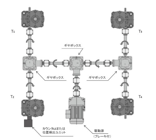
連動用駆動源必要容量Ptを算出し、駆動源を選定
1. 駆動源の総必要トルクTtの算出
各ジャッキ1台あたりの駆動源側での必要トルクT1~4を求め、それらを合計し駆動源の総必要トルクTtを求めます。
[ジャッキ1台あたりの必要トルク]
T1~4 = T (ギヤボックス効率) ギヤボックスの台数
[駆動源の総必要トルク]
Tt = T1 + T2 + T3 + T4
T1~4:各ジャッキの駆動源側での必要トルク N・m{kgf・m}
T:ジャッキ本体の必要入力トルク N・m{kgf・m}
ギヤボックス効率:一般的に0.9とします。
Tt:駆動源の総必要トルク N・m{kgf・m}
4台連動(図1)の場合、T1~4 = T0.92となります。
図1
2. 許容入力軸トルクの確認
ジャッキの必要入力トルクが選定したジャッキの許容入力軸トルク以下であることを確認します。
例)
ジャッキの配置が図2のようにストレート形の場合、駆動源側のジャッキには2台分の必要入力トルクが入力軸に伝達されます。
この2台分のトルクが許容入力軸トルク以下であるか確認します。
図2
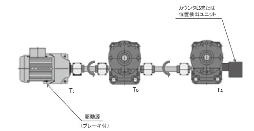
ジャッキAのみの必要トルクTA
ジャッキBのみの必要トルクTB
駆動源必要トルクTt = TA + TB < 許容入力軸トルク
3. 駆動源必要容量Ptの算出
入力回転速度Nと1で求めた総必要トルクTtより駆動源必要容量Ptを求めます。
SI単位 Pt = Tt×N 9550
重力単位 Pt = Tt×N 974
Pt:駆動源必要容量 kW
Tt:駆動源の総必要トルク N・m{kgf・m}
N:ジャッキの入力回転速度 r/min
その他の機器の選定
ギヤボックス
入力回転速度と許容トルクより選定します。
つばきマイタギヤボックスの単冊カタログをご参照ください。
カップリング
許容トルクと最大軸径より選定します。
つばきカップリングの単冊カタログをご参照ください。
リニパワージャッキの選定例
例題:
4台連動押上リフタ(レイアウトは下図の4台連動パターンと同様)工場内常温、粉塵若干有り
横荷重対策はリフタ装置側にてガイド設置、ベース固定-軸端支持/固定の据付状態、電源は三相220V/60HZ
使用頻度は2回作動/時間×8時間/日×300日/年×3年使用
- (1)最大荷重:98.0kN{10tf}/4台
- (2)必要速度:5mm/s(0.3m/min)
- (3)使用ストローク:260mm
4台連動パターン
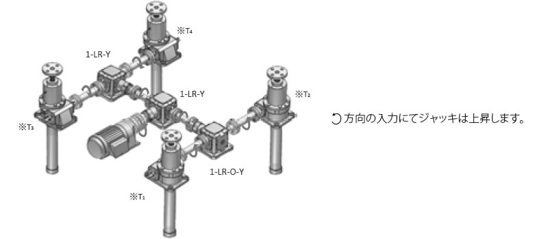
※T1~4は上記参照
| SI単位 |
|---|
|
| {重力単位} |
|---|
|
周辺機器の選定例
A. 駆動源の決定
1. 各ジャッキの駆動源側での必要トルクT1(2.3.4)
ジャッキ4台とも分散経路は同じなので
SI単位 Tt = T1×4 = 83.5N・m
重力単位 Tt = T1×4 = 8.52kgf・m
2. ジャッキの最大許容入力軸トルクの検討
今回の連動パターンではジャッキが直列に2台以上並んでいないので検討不要。
3. 駆動源必要容量Pt
また入力回転数180r/minより
1800 180 = 10以上より2.2kWブレーキ付ギヤモートル つばきGMTR221-42L10Bを選定します。
詳細はつばき小形ギヤモータカタログをご参照ください。
B.1.ギヤボックスは、入力回転速度180r/min、
ジャッキ必要入力トルク15.4N・m{1.57kgf・m }より
1-1.ジャッキ側左右のギヤボックスは、ジャッキ2台分のトルク
20.9×2
0.9
= 46.4N・m
2.13×2
0.9
= 5.11kgf・m
をクリアするギヤボックスED4Mを選定します。
(ただし、ギヤボックスの回転方向にご注意ください。)
1-2.ギヤモートル側ギヤボックスはジャッキ4台分ですのでトルク
20.9×4
0.92
= 103N・m
2.13×4
0.92
= 8.69kgf・m
をクリアするギヤボックスED6Mが選ばれます。
ジャッキ側ギヤボックス
- 左側:ED4M 1-LR-O-Y
- 右側:ED4M 1-LR-Y
ギヤモートル側ギヤボックス
- ED6M 1-LR-Y
(詳細はつばきマイタギヤボックスカタログをご参照ください)
B.2.装置条件に合わせて各種カップリングをお選びください。
(詳細はつばきカップリングカタログをご参照ください)
検討方法としては
2-1ジャッキ-ギヤボックス間は、ジャッキ必要入力トルク16.9N・m{1.73kg・fm}およびジャッキ入力軸径(JWB050USHはΦ20)、ギヤボックス軸直径(ED4MはΦ19)よりお選びください。
必要数は2×2×2 = 8個となります。
2-2ギヤボックス相互間は、ジャッキ2台分のトルク
20.9×2 0.9 = 50.1N・m 2.13×2 0.9 = 5.11kgf・mおよびジャッキ側ギヤボックス軸径(ED4MはΦ19)、ギヤモートル側ギヤボックス軸径(ED6MはΦ25)よりお選びください。
必要数は2×2 = 4個となります。
2-3ギヤボックス-ギヤモートル間は、ジャッキ4台分のトルク
20.9×4 0.92 = 85.2N・m 2.13×4 0.92 = 8.69kgf・mおよびギヤボックス軸径(ED6MはΦ25)、ギヤモートル出力軸径(GMTR221-42L10BはΦ42)よりお選びください。必要数は2個です。
