技術資料 直動機器 リニパワージャッキ 技術資料
許容座屈荷重
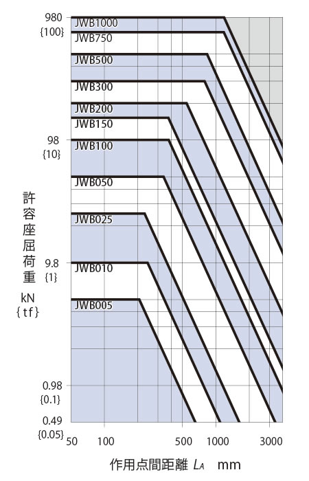
- ・圧縮荷重で使用する場合は、このグラフより座屈荷重に対するジャッキ枠番を決定してください。
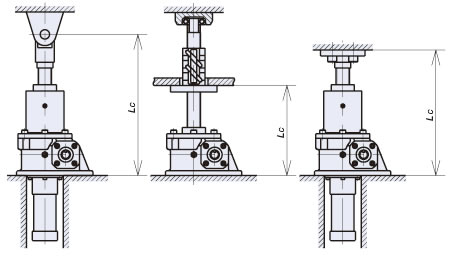
座屈選定グラフは座屈安全率Sf=4を見込んだグラフです。- (1)下図A、C据付状態から作用点間距離LA, LCを選択してください。
(下図の据付状態以外はこちらをご参照ください) - (2)ジャッキ1台あたりの荷重W(縦軸)と作用点間距離(横軸)の交点からジャッキの枠番をお選びください。
- (1)下図A、C据付状態から作用点間距離LA, LCを選択してください。
- ・横荷重はかからないようにしてください。
下に示す座屈選定グラフには横荷重は考慮していません。 - ・据付状態としては、ネジ軸が引張荷重となるような構造で装置を工夫していただければ、座屈がなく、経済的です。
A ベース固定一軸端フリー
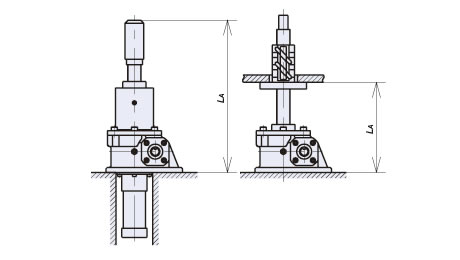
C ベース固定一軸端支持/固定
| 作用点間距離 LA mm | 作用点間距離 LC mm | |
|---|---|---|
| JWB (ボールネジタイプ) |
 [クリックで拡大] |
 [クリックで拡大] |
| JWH (ハイリードボールネジタイプ) |
- | 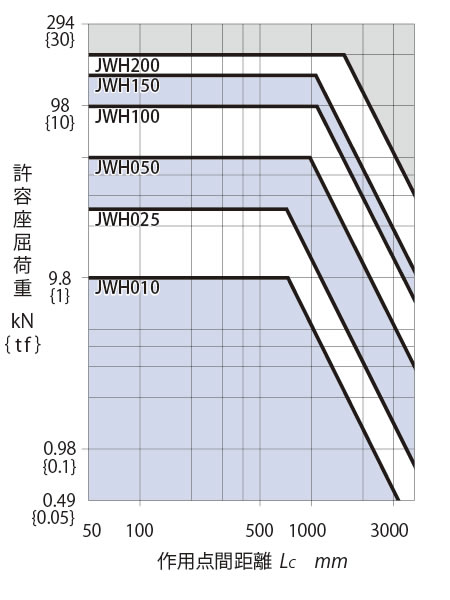 [クリックで拡大] |
| JWM (台形ネジタイプ) |
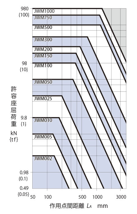 [クリックで拡大] |
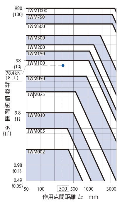 [クリックで拡大] |
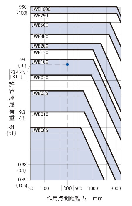
- 注)
- 1.このグラフの----線は荷重W78.4kN{8tf}、(座屈安全率Sf=4)で据付状態Cの作用点間距離300mmという例を示しています。
この場合では、縦軸・横軸の交点を満足するジャッキJWB100/JWM100が選定できます。 - 2.詳細な検討が必要な場合は、計算(こちら)にてご確認ください。
