技術資料 減速機 ウォーム減速機 モータ仕様
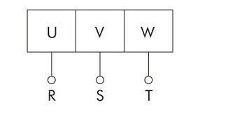
結線
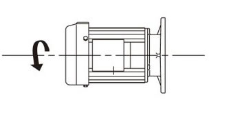
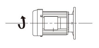
1. 回転方向
| モータ容量 | 接続 | 回転方向 | 接続 | 回転方向 |
|---|---|---|---|---|
| 0.1kW ~ 5.5kW |
 |
 |
 |
 |
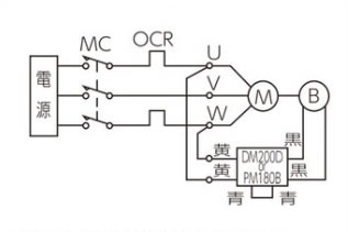
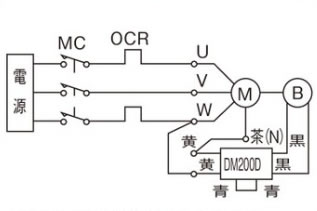
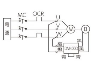
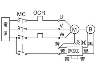
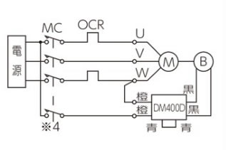
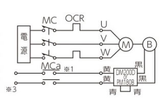
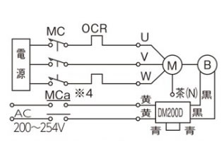
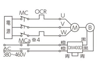
2. ブレーキ付モータの結線
- ・標準品は交流同時切りで出荷しています。
- ・結線によって応答時間が異なりますので、下図参考のうえ用途に応じて選択してください。
| 用途 | 三相 200V | 三相 400V | |||
|---|---|---|---|---|---|
| 0.1kW ~ 5.5kW | 0.1kW ~ 0.4kW | 0.75kW ~ 3.7kW | 5.5kW | ||
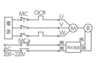
| 交流同時切り |
|
5.5kWのみPM180Bとなります。 |
 |
 |
- |
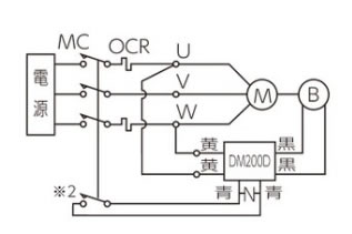
| 交流別切り |
|
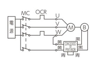
5.5kWのみPM180Bとなります。 |
 |
 |
- |
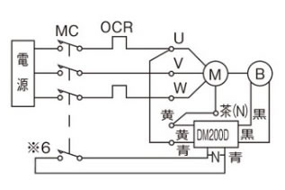
| 交流別操作 |
|
※3印部のブレーキの供給電圧は、0.1kW・0.2kWはAC200V~AC254V |
注・閉端接続子で配線している茶(N)は端子台から必ず絶縁してください。 |
 |
 |
| 直流別切り |
|
PM180Bは直流切りできません。 |
 |
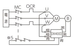 |
- |
- M:モータ
- B:ブレーキ
- MC:電磁接触器
- MCa:補助継電器
- OCR:過電流継電器 DM200D、PM180B、DM400D
- -N-:保護素子(バリスタ)
- 注1)ブレーキ電圧はDC90Vです。(DM200DおよびPM180BにAC200V入力時)
- 注2)直流別切りにてご使用の場合は、配線の長さ・配線の方法・リレーの種類などによってブレーキ用電源モジュールが破損する場合がありますので、直流別切り用端子間にバリスタを接続してください。ブレーキ用電源モジュールの近く(青リード線部)に接続するほうが効果的です。具体的なバリスタの形番は下記の通りですが、相当品のバリスタでも使用可能です。バリスタ電圧はDM200Dは470Vのものを選定してください。(DM400Dはバリスタ内蔵形なので外部に取付不要です)
商品名 メーカ 形番 DM200Dの時 サージアブソーバ パナソニック(株) ERZV14D471 セラミックバリスタ 日本ケミコン(株) TND14V-471KB00AAA0 - 注3)※1の補助継電器(MCa)は接点容量AC200V7A以上(抵抗負荷)のものをご使用ください。
※2にMCの補助接点あるいは補助継電器をご使用の場合は接点容量AC200V10A以上(抵抗負荷)としてください。 - 注4)※4の補助継電器(MCa)は接点電圧AC400~440V誘導負荷1A以上のものをご使用ください。
- 注5)※5の補助継電器(MCa)は接点電圧AC400~440V誘導負荷1A以上のものを直列に2個または3個接続してご使用ください。
