技術資料 トップチェーン 選定
選定手順や注意事項等をご覧になりたい方は下記へお進みください。
製品シリーズの絞り込みや仮選定をご希望の方は
こちらをクリックしてください。
使用条件が決まっており詳細な選定をご希望の方は
こちらをクリックしてください。
プラスチックモジュラーチェーン(幅広)の選定手順
下記手順に沿って、搬送条件に最も適したプラスチックモジュラーチェーン(幅広)と走行レールの選定を行ってください。
(各項目をクリックすると本文にスクロールできます。)
注)
- 1. BTM8H形、WT2515F-W形、WT3109-W形、BTH16形、低温(LTW)仕様を選定される場合はお問合せシートをご記入の上当社までお問合せください。
- 2. WT2250VG形、 WT2250形フライトタイプを選定される場合は当社までお問合せください。
手順1. 搬送条件の確認
搬送条件の確認を行ってください。
搬送条件確認項目
| 1.搬送物 | (1)材質 |
|---|---|
| (2)1個当たりの質量 g/個 | |
| (3)形状 | |
| (4)寸法(縦×横×高さ)(直径Φ×高さ) mm | |
| (5)搬送方向 | |
| 2.搬送経路 | (1)直線搬送・曲線搬送 |
| (2)コンベヤ長さ m | |
| (3)コンベヤ幅 mm | |
| (4)搬送レイアウト | |
| (5)スペース m | |
| 3.搬送条件 | (1)搬送量 BPM・個 |
| (2)搬送間隔 mm | |
| (3)コンベヤ速度 m/min | |
| (4)潤滑の有無 | |
| (5)搬送物のストックの有無(アキュムレートの有無、割合)(有の場合、アキュムレートの長さ:m) | |
| 4.使用条件 | (1)温度 ℃ |
| (2)薬品、水、湿度などの腐食条件(各種液体に対する耐食性参照)(有の場合、液体名称) | |
| (3)ガラス破片、塗装屑、金属粉、砂などの摩耗促進物の有無 | |
| (4)紫外線照射の有無 |
2-(3)搬送レイアウト・その他メモ
手順2. チェーン仕様の選定
チェーン仕様については使用雰囲気と用途より選択してください。
注)
- 1. チェーン形式のチェーンピッチや、対応チェーン仕様、使用温度範囲は各商品ページを参照ください。
- 2. 耐食性は各種液体に対する耐食性を参照ください。
手順3. 走行レール材質の選定
チェーン仕様から適切な走行レール材質を選択してください。
表1. 走行レール材質の選定表
| チェーン | 走行レール材質 | 潤滑 | |||
|---|---|---|---|---|---|
| 無 | 有 | ||||
| 摩耗性介在物 | |||||
| 無 | 有 | 無 | 有 | ||
| プラスチックモジュラーチェーン(幅広) ・直線搬送用 ・曲線搬送用 |
ステンレス | B | D | A | A |
| スチール | A | C | B | B | |
| プラレール(Pレール) | D | × | A | × | |
| PLFレール | B | × | A | × | |
| Mレール SJ-CNO |
A | × | × | × | |
注)
- 1. 「A」:特に推奨、「B」:推奨、「C」:可の中での推奨、「D」:可、「×」:不適当。
- 2. 耐熱・高速(KV)仕様の場合は、常温ではステンレスまたはスチール製 走行レールとし、高温ではステンレス製走行レールとしてください。
- 3. 推奨金属走行レール=冷間圧延材。
- 4. スチールレールは油潤滑の場合を示しています。
プラレールの材質・外観色・特長
| 材質・外観色 | 特長 | |
|---|---|---|
| プラレール (Pレール) |
超高分子量ポリエチレン (外観色:白色または緑色) |
・最も一般的なレール ・削加工または押出成形品 ・プラスチックトップチェーンの場合、ウェット条件での使用推奨 ・吸水性が少なく、耐薬品性、耐衝撃性にも優れます。 |
| PLFレール | 低摩擦・耐摩耗性 超高分子量ポリエチレン (外観色:白色) |
・Pレールよりも低摩擦で耐摩耗性があるレール ・削加工または押出成形品 |
| Mレール SJ-CNO |
特殊ポリアミド (Mレール:外観色:青色) (SJ-CNO:外観色:紫色) |
・ドライ条件専用レール ・耐摩耗性があるレール ・削加工品 |
注)使用温度範囲
プラレール(Pレール)、PLFレール:-20℃~60℃
Mレール・SJ-CNO:-20℃~80℃
手順4. 係数の決定
表2の各係数は、当社内の実験データに基づいています。
使用条件や使用雰囲気、搬送物の形状や材質(仕様)、チェーンの汚れ方などによって差異が生じることがあります。
各係数は手順5の張力計算に使用してください。
表2. プラスチックモジュラーチェーンと相手材の動摩擦係数(μ1, μ2)
| 相手材 | 潤滑条件 | トッププレート仕様 | |||||||||||
|---|---|---|---|---|---|---|---|---|---|---|---|---|---|
| クローズタイプ、オープンタイプ | ネットタイプ | DIA | DIY | ||||||||||
| 普通 注)5 | LFB, NLF, MWS, CB, WR, HG |
ALF | KV150 | KV250 | HTW | MF | LFB, MWS |
ALF | |||||
| 走行レール 材質(μ1) |
プラレール (Pレール) Mレール |
ドライ・水 | 0.25 | 0.20 | 0.15 | - | - | 0.30 | 0.27 | 0.20 | 0.15 | 0.30 | 0.25 |
| 石鹸水・油 | 0.15 | 0.13 | 0.11 | - | - | 0.20 | - | 0.13 | 0.11 | - | 0.12 | ||
| SJ-CNO | ドライ・水 | 0.20 | 0.15 | 0.13 | - | - | - | - | 0.15 | 0.13 | 0.30 | 0.20 | |
| 石鹸水・油 | 0.12 | 0.12 | 0.11 | - | - | - | - | 0.12 | 0.11 | - | 0.12 | ||
| PLFレール | ドライ・水 | 0.18 | 0.14 | 0.12 | - | - | - | - | 0.14 | 0.12 | - | - | |
| 石鹸水 | 0.12 | 0.12 | 0.11 | - | - | - | - | 0.12 | 0.11 | - | - | ||
| スチール・ ステンレス |
ドライ・水 | 0.25 | 0.20 | 0.14 | 0.25 | 0.35 | 0.32 | 0.27 | 0.20 | 0.14 | 0.30 | 0.25 | |
| 石鹸水・油 | 0.15 | 0.15 | 0.11 | - | - | 0.20 | - | 0.15 | 0.11 | - | 0.12 | ||
| 搬送物 材質(μ2) |
金属缶 | ドライ・水 | 0.25 | 0.20 | 0.14 | 0.23 | 0.35 | 0.35 | 0.28 | 0.13 | 0.10 | 0.30 | 0.25 |
| 石鹸水・油 | 0.14 | 0.13 | 0.11 | - | - | 0.20 | - | 0.12 | 0.10 | - | 0.12 | ||
| ガラスビン | ドライ・水 | 0.22 | 0.14 | 0.10 | 0.18 | 0.35 | 0.22 | 0.25 | 0.11 | 0.10 | 0.25 | 0.22 | |
| 石鹸水・油 | 0.14 | 0.14 | 0.10 | - | - | 0.10 | - | 0.11 | 0.10 | - | 0.12 | ||
| プラ容器 | ドライ・水 | 0.25 | 0.17 | 0.13 | 0.20 | - | 0.30 | 0.28 | 0.11 | 0.10 | 0.30 | 0.25 | |
| 石鹸水・油 | 0.15 | 0.13 | 0.11 | - | - | 0.20 | - | 0.11 | 0.10 | - | 0.15 | ||
| 紙パック | ドライ・水 | 0.31 | 0.29 | 0.22 | 0.35 | - | 0.35 | 0.38 | 0.20 | 0.15 | 0.38 | 0.30 | |
| 石鹸水・油 | 0.20 | 0.21 | 0.12 | - | - | - | - | 0.19 | 0.11 | - | 0.20 | ||
注)
- 1. 常温(50℃以下)での動摩擦係数です。高温(50℃を超える)の場合は動摩擦係数0.35を適用してください。
- 2. 上表の動摩擦係数データは当社実験によるものです。摩擦係数値はチェーンの汚れ、搬送物の底面形状などにより若干の差異が生じます。
特に紙パック、紙缶は底面形状、紙材質などにより摩擦係数値に大きな差が生じますので搬送物毎に摩擦係数の測定をお勧め致します。 - 3. MレールとSJ-CNOはドライ条件専用走行レールです。
- 4. 水潤滑の場合、搬送物の種類によっては表2の値より大きくなり吸着現象が生じる場合があります。
- 5. 対象:普通仕様、耐薬品(Y)仕様、導電(E)仕様、耐酸(AR)仕様、耐紫外線(UVR)仕様。
表3. 曲線用走行レール使用時の角度係数(αL)、長さ係数(αS)
| トッププレート材質 | 潤滑状態 | 横曲り角度 | ||||||||
|---|---|---|---|---|---|---|---|---|---|---|
| 30° | 45° | 60° | 90° | 120° | 150° | 180° | ||||
| 角度係数(αL) | ポリアセタール | B | 潤滑なし・水潤滑 | 1.15 | 1.22 | 1.30 | 1.50 | 1.70 | 1.90 | 2.20 |
| 石鹸水潤滑 | 1.10 | 1.13 | 1.15 | 1.25 | 1.35 | 1.50 | 1.60 | |||
| LFG | 潤滑なし・水潤滑 | 1.10 | 1.17 | 1.25 | 1.35 | 1.50 | 1.70 | 1.85 | ||
| 石鹸水潤滑 | 1.10 | 1.11 | 1.15 | 1.25 | 1.35 | 1.50 | 1.60 | |||
| HTW | 潤滑なし・水潤滑 | 1.20 | 1.27 | 1.45 | 1.75 | 2.10 | 2.50 | 3.00 | ||
| 石鹸水潤滑 | 1.10 | 1.17 | 1.25 | 1.35 | 1.50 | 1.70 | 1.85 | |||
| 長さ係数(αS) | 0.5 | 0.8 | 1.0 | 1.6 | 2.1 | 2.6 | 3.1 | |||
注)フライトタイプの傾斜搬送においては、傾斜角に応じた上記係数を適用ください。
手順5. チェーンに作用する張力の計算
下記の公式に基づき、一般コンベヤのチェーンに作用する張力と所要動力の計算を行ってください。
注)特殊コンベヤ(パストライザ・ウォーマ・クーラ)、ノーズバーコンベヤ(従動側、前方側、両端)、正逆底部駆動、傾斜搬送の張力計算例を参照ください。
注)SI単位と重力単位
計算式はSI単位と、重力単位を併記しています。
重力単位で張力Fを計算する場合、重力単位の重量(kgf)はSI単位の質量(kg)と同一の数値です。
記号の説明
- F = チェーンに作用する張力 kN{kgf}
- m1 = チェーン概略質量 (kg/m)
「チェーン概略質量算出方法」
1m長さあたりのチェーン概略質量を算出します。
使用を検討しているチェーン幅をAmmとした場合
m1 = チェーン概略質量(カタログ値(kg/m2)) × A/1000
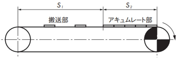
- S1 = 搬送部の長さ (m)
- m2 = 搬送部の搬送物質量 (kg/m)
- S2 = アキュムレート部の長さ (m)
- m3 = アキュムレートの搬送物質量 (kg/m)
- μ1 = チェーンと走行レールの動摩擦係数 (表2参照)
- μ2 = アキュムレート部のチェーンと搬送物の動摩擦係数 (表2参照)
- P = 所要動力 (kW)
- V = チェーン速度 (m/min)
- η注) = 駆動部の伝達機械効率
SI単位(kN)
チェーンに作用する張力......(1)
F = 9.80665 × 10⁻³ { (2.1m1 + m2) S1・μ1 + (2.1m1 + m3) S2・μ1 + m3・S2・μ2 }
所要動力
P = F・V 60η注)
重力単位(kgf)
チェーンに作用する張力......(1)
F = (2.1m1 + m2) S1・μ1 + (2.1m1 + m3) S2・μ1 + m3・S2・μ2
所要動力
P = F・V 6120η注)
注)
- 1. 伝達機械効率は、使用される駆動装置をご確認ください。
- 2. プラスチックモジュラーチェーン(固定幅)はトップチェーンの選定手順に従い、選定を行ってください。
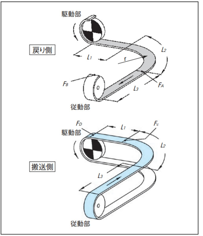
曲線搬送(曲線部1箇所)の計算
基本的には、直線搬送の場合と同様です。コーナ部の作用張力は角度係数により補正します。
下図の搬送経路について計算例を示します。
曲線搬送の場合はチェーンに作用する張力Fに加えて、曲線部でチェーンに作用する張力Fαを計算します。
チェーンと走行レールが摺動する曲線搬送では潤滑されることを推奨します。
特に90°を超える横曲り角度の場合は、比較的短期間でチェーンまたは走行レールが偏摩耗し、チェーンが浮上がる可能性があります。
F = 9.80665 × 10⁻³ ・FD (kN) ... (1)
戻り側張力
[A部張力:FA]
FA = m1(L1 + L2) μ1・αL 90°
L2 = r × αS 90°
[B部張力:FB]
FB = 1.1 ×(FA + m1・L3・μ1)
搬送側張力
[C部張力:FC]
FC ={FB + (m1 + m2) (L2 + L3) μ1 + m3 (L2 + L3) μ2}・αL 90°
L2 = r × αS 90°
[曲線部のチェーンに作用する張力:Fα]
Fα = Fc × 2
Fαが、チェーン曲線部の最大許容張力以下であれば使用可能です。曲線部の最大許容張力は、曲線搬送チェーン能力線図を参考にコンベヤ速度および使用雰囲気温度を加味して算出してください。チェーン能力線図は各製品ページを参照ください。
[D部張力:FD]
FD = FC + {(m1 + m2) L1・μ1 + m3・L1・μ2}
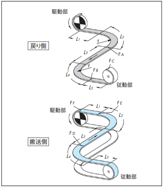
曲線搬送(曲線部2箇所)の計算
曲線部を走行レールなどで摺動させる場合は、90度カーブ2箇所までとしてください。チェーンの脈動の原因となります。
より多くの曲線部を設置したい場合は、コンベヤの分割を検討してください。
曲線搬送の場合はチェーンに作用する張力Fに加えて、曲線部でチェーンに作用する張力Fαを計算します。
F = 9.80665 × 10⁻³ ・FF (kN) ... (1)
戻り側張力
[A部張力:FA]
FA = m1(L1 + L2) μ1・αL 90°
L2 = r × αS 90°
[B部張力:FB]
FB = {FA + m1(L3 + L4) μ1} αL 90°
L4 = r × αS 90°
[C部張力:FC]
FC = 1.1 × (FB + m1・L5・μ1)
搬送側張力
[D部張力:FD]
FD = {FC + (m1 + m2) (L4 + L5) μ1 + m3(L4 + L5) μ2}・αL 90°
L4 = r × αS 90°
[E部張力:FE]
FE = {FD + (m1 + m2) (L2 + L3) μ1 + m3(L2 + L3) μ2}・αL 90°
L2 = r × αS 90°
[曲線部のチェーンに作用する張力:Fα]
Fα = FE × 2
Fαが、チェーン曲線部の最大許容張力以下であれば使用可能です。曲線部の最大許容張力は、曲線搬送チェーン能力線図を参考にコンベヤ速度および使用雰囲気温度を加味して算出してください。チェーン能力線図は各製品ページを参照ください。
[F部張力:FF]
FF = FE + {(m1 + m2) L1・μ1 + m3・L1・μ2}
傾斜搬送(傾斜のみ)の計算
注)SI単位と重力単位
計算式はSI単位と、重力単位を併記しています。
重力単位で張力Fを計算する場合、重力単位の重量(kgf)はSI単位の質量(kg)と同一の数値です。
記号の説明
- F = チェーンに作用する張力 kN{kgf}
- m1 = チェーン概略質量 (kg/m)
「チェーン概略質量算出方法」
1m長さあたりのチェーン概略質量を算出します。
使用を検討しているチェーン幅をAmmとした場合
m1 = チェーン概略質量(カタログ値(kg/m2)) × A/1000
- m2 = 搬送部の搬送物質量 (kg/m)
- μ1 = チェーンと走行レールの動摩擦係数 (表2参照)
- αL = 水平と傾斜間のカーブ部の角度係数 (表3参照)
- αS = 長さ係数 (表3参照)
- θ = 傾斜角度 (度)
- r = 水平と傾斜間のカーブ部の半径 (m)
- P = 所要動力 (kW)
- V = チェーン速度 (m/min)
- η注) = 駆動部の伝達機械効率
注)伝達機械効率は、使用される駆動装置をご確認ください。
表4. 傾斜搬送角度の目安
| チェーン材質 | 潤滑なし(ドライ) | 石鹸水潤滑 | 油潤滑 |
|---|---|---|---|
| スチール系 | 10度 | - | 6度 |
| 普通仕様(ポリアセタール) | 5度 | 3度 | - |
| ラバータイプ | 20度 | - | - |
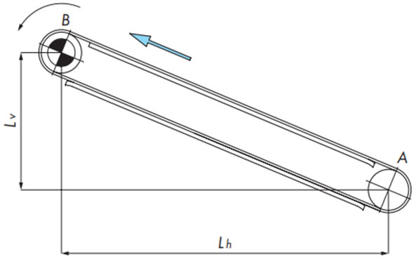
F = 9.80665 × 10⁻³ ・FB (kN) ... (1)
戻り側張力
[A部張力:FA]
FA = 1.1m1 (Lh・μ1 - Lv)
FA < 0の場合は、FA = 0
搬送側張力
[B部張力:FB]
FB = FA + {(m1 + m2) (Lh・μ1 + Lv)}
チェーン張力
F = FB
手順6. チェーン形式と幅の決定
- (1)式で求めたチェーンに作用する張力F(kN)を、チェーン幅1m当たりの作用張力F'(kN/m)に換算します。
F' =
1000F
チェーン幅(mm)
...... (2)
- (2)式で求めたチェーン幅1mあたりの作用張力F'よりも大きな最大許容張力のプラスチックモジュラーチェーンの形式と幅を選定してください。
注)
- 1. ウェット条件の場合は、使用温度:max60℃です。(高温(HTW)仕様のみmax105℃。耐熱・高速(KV250)仕様のみmax250℃。耐熱・高速(KV150)仕様は使用不可。)
- 2. チェーンの最大許容張力は、能力線図を参考にコンベヤ速度および使用雰囲気温度を加味して算出してください。能力線図は各製品ページを参照ください。
- 3. 最大許容張力が不足している場合は、さらに大きなチェーンを選択する方法もあります。また、コンベヤの使用環境も考慮してチェーン形式を決定してください。
F' = 1000F チェーン幅(mm) ...... (2)
注)
- 1. ウェット条件の場合は、使用温度:max60℃です。(高温(HTW)仕様のみmax105℃。耐熱・高速(KV250)仕様のみmax250℃。耐熱・高速(KV150)仕様は使用不可。)
- 2. チェーンの最大許容張力は、能力線図を参考にコンベヤ速度および使用雰囲気温度を加味して算出してください。能力線図は各製品ページを参照ください。
- 3. 最大許容張力が不足している場合は、さらに大きなチェーンを選択する方法もあります。また、コンベヤの使用環境も考慮してチェーン形式を決定してください。
