技術資料 トップチェーン 選定
このページの後半では以下の選定例についても紹介しています。
(各項目をクリックすると本文にスクロールできます。)
- *WT0700シリーズ選定例
- *WT1500シリーズ、WT1510シリーズ、BTN5形選定例
- *WT2525VG-K形選定例
- *WT1515F-W形、WT1516F-W形選定例
- *WT3816-K形選定例
プラスチックモジュラーチェーン(幅広)の選定例
手順1. 搬送条件の確認
- ・搬送幅...約600mm
- ・コンベヤ機長...10m
- ・搬送速度...20m/min
- ・搬送物...350ml実缶(98kg/m2)
- ・アキュムレート...コンベヤ上フルアキュムレート
- ・温度...常温
- ・潤滑...石鹸水潤滑
手順2. チェーン仕様の選定
低摩擦・耐摩耗(LFB)仕様、オープンタイプを選定
(BTO6-6096-LFB)
手順3. 走行レール材質の選定
超高分子量ポリエチレンを選定
(BTO6-6096-LFB)
手順4. チェーンに作用する張力の計算
- m1=チェーン概略質量...4kg/m
チェーン幅609.6mmのため
6.56(カタログ値kg/m2)× 609.6/1000 ≒ 4(kg/m) - S1=搬送部の長さ...0m
- m2=搬送部の搬送物質量...0kg/m
- S2=アキュムレート部の長さ...10m
- m3=アキュムレート部の搬送物質量...60kg/m
チェーン幅609.6mmのため
98(上記条件kg/m2) × 609.6/1000 ≒ 60(kg/m) - μ1=チェーンと走行レールの動摩擦係数...0.13(表2参照)
- μ2=アキュムレート部のチェーンと搬送物の摩擦係数...0.13(表2参照)
- V=チェーン速度...20m/min
- η=駆動部の伝達機械効率...0.8
SI単位(kN)
F = 9.80665 × 10⁻³ × {(2.1 × 4 + 0) × 0 × 0.13
+ (2.1 × 4 + 60) × 10 × 0.13 + 60 × 10 × 0.13} = 1.64kN
P = 1.64 × 20 60 × 0.8 = 0.683kW
重力単位
F = (2.1 × 4 + 0) × 0 × 0.13 + (2.1 × 4 + 60) × 10 × 0.13
+ 60 × 10 × 0.13 = 166.9kgf
P = 166.9 × 20 6120 × 0.8 = 0.682kW
手順5. チェーン形式と幅の決定
1m幅換算張力
F' =
1000 × 1.64
609.6
= 2.69kN/m {274kgf/m}
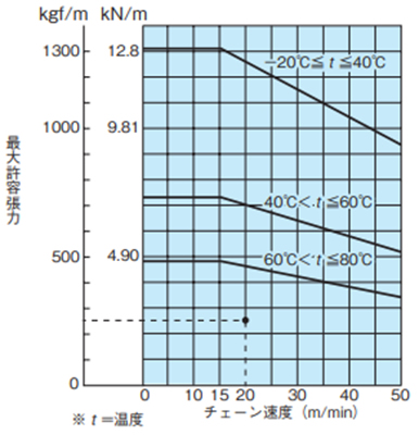
能力線図により使用可能(能力線図は各製品ページを参照ください。)
手順6. スプロケット、シャフト、ベアリングユニットの選定
スプロケット、シャフト、ベアリングユニットの選定
ベアリング支持スパン = チェーン幅(610) + 150 = 760mm
1m幅換算能力(F')とベアリング支持スパンの関係グラフおよびシャフト仕様と常用されるベアリングユニット(表13、37、38より)
10T・38六角シャフト ベアリングユニットΦ25~Φ35
または
24T・40四角シャフト ベアリングユニットΦ30~Φ35
のいずれかを使用します。
手順7. チェーンに作用する張力の計算
1) チェーン張力負荷率F1(%)の確認
F1 = 100 × 2.69 12.8 = 21.0%
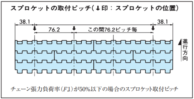
2) スプロケット取付ピッチの決定
F1は50%以下であるため4-3項の(8)より、スプロケットは以下のピッチで取付けます。
WT0700シリーズ選定例
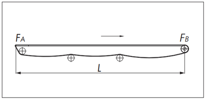
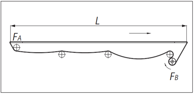
従動側ノーズバー
●計算式(SI単位:kN)
・戻り側張力
[A部張力:FA]
FA = m1・L・μ1・fn × 9.80665 × 10⁻³
・搬送側張力
[B部張力:FB]
FB = FA + {(m1 + m2) L・μ1 + m2・LS・μ2} × 9.80665 × 10⁻³
・チェーン張力
F = FB
※)搬送物のアキュームが無い場合は、LS = 0
●計算例(SI単位)
| 使用条件 | |
|---|---|
| チェーン形式 | WT0705-W300-LFG (m1=5.9×0.3=1.77kg/m) |
| チェーン幅 | 300mm |
| レイアウト | L=2m |
| チェーン速度 | V=15m/min |
| 搬送物 | アルミ缶500ml(実) |
| 搬送物質量(1m長さ当たり) | m2=139kg/m2(523g/個) ×0.3m=41.7kg/m |
| 走行レール | 超高分子量ポリエチレン (プラレール) |
| アキューム距離 | Ls=2m |
| 潤滑 | ドライ |
| 使用雰囲気温度 | 20℃ |
| チェーンと走行レールの動摩擦係数 | μ1=0.2 |
| チェーンと搬送物との動摩擦係数 | μ2=0.2 |
| ノーズバー係数 | fn=1.8 |
・戻り側張力
[A部張力:FA]
FA = 1.77 × 2 × 0.2 × 1.8 × 9.80665 × 10-3 = 0.0125kN
・搬送側張力
[B部張力:FB]
FB = 0.0125 + {(1.77 + 41.7) × 2 × 0.2 + 41.7 × 2 × 0.2} × 9.80665 × 10-3 = 0.35kN
・使用判定
最大許容張力≧FB'
チェーン幅1m当たりに換算する
FB' = 1000 × FB 300 = 1.17(kN/m)
能力線図より許容張力は2.5(kN/m)
2.5(kN/m)≧1.17(kN/m)
選定チェーンは使用可能です。
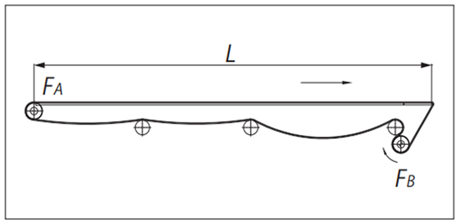
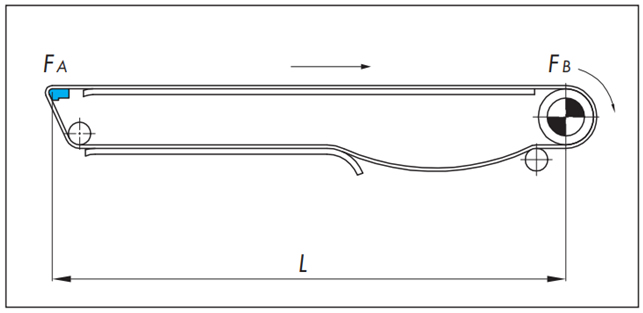
前方側ノーズバー
●計算式(SI単位:kN)
・戻り側張力
[A部張力:FA]
FA = 1.1m1・L・μ1 × 9.80665 × 10-3
・搬送側張力
[B部張力:FB]
FB= [FA + {(m1 + m2) L・μ1 + m2・LS・μ2} × 9.80665 × 10⁻³] × fn
・チェーン張力
F = FB
※)搬送物のアキュームが無い場合は、LS = 0
●計算例(SI単位)
| 使用条件 | |
|---|---|
| チェーン形式 | WT0705-W300-LFG (m1=5.9×0.3=1.77kg/m) |
| チェーン幅 | 300mm |
| レイアウト | L=2m |
| チェーン速度 | V=15m/min |
| 搬送物 | アルミ缶500ml(実) |
| 搬送物質量(1m長さ当たり) | m2=139kg/m2(523g/個) ×0.3m=41.7kg/m |
| 走行レール | 超高分子量ポリエチレン (プラレール) |
| アキューム距離 | Ls=2m |
| 潤滑 | ドライ |
| 使用雰囲気温度 | 20℃ |
| チェーンと走行レールの動摩擦係数 | μ1=0.2 |
| チェーンと搬送物との動摩擦係数 | μ2=0.2 |
| ノーズバー係数 | fn=1.8 |
・戻り側張力
[A部張力:FA]
FA = 1.1 × 1.77 × 2 × 0.2 × 9.80665 × 10-3 = 0.0077kN
・搬送側張力
[B部張力:FB]
FB = [0.0077 + {(1.77 + 41.7) × 2 × 0.2 + 41.7 × 2 × 0.2} × 9.80665 × 10-3] × 1.8 = 0.62kN
・使用判定
最大許容張力≧FB'
チェーン幅1m当たりに換算する
FB' = 1000 × FB 300 = 2.07(kN/m)
能力線図より許容張力は2.5(kN/m)
2.5(kN/m)≧2.07(kN/m)
選定チェーンは使用可能です。
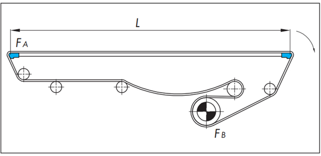
両端ノーズバー
●計算式(SI単位:kN)
・戻り側張力
[A部張力:FA]
FA = m1・L・μ1・fn × 9.80665 × 10⁻³
・搬送側張力
[B部張力:FB]
FB= [FA + {(m1 + m2) L・μ1 + m2・LS・μ2} × 9.80665 × 10⁻³] × fn
・チェーン張力
F = FB
※)搬送物のアキュームが無い場合は、LS = 0
●計算例(SI単位)
| 使用条件 | |
|---|---|
| チェーン形式 | WT0705-W300-LFG (m1=5.9×0.3=1.77kg/m) |
| チェーン幅 | 300mm |
| レイアウト | L=2m |
| チェーン速度 | V=15m/min |
| 搬送物 | アルミ缶500ml(実) |
| 搬送物質量(1m長さ当たり) | m2=139kg/m2(523g/個) ×0.3m=41.7kg/m |
| 走行レール | 超高分子量ポリエチレン (プラレール) |
| アキューム距離 | Ls=2m |
| 潤滑 | ドライ |
| 使用雰囲気温度 | 20℃ |
| チェーンと走行レールの動摩擦係数 | μ1=0.2 |
| チェーンと搬送物との動摩擦係数 | μ2=0.2 |
| ノーズバー係数 | fn=1.8 |
・戻り側張力
[A部張力:FA]
FA = 1.77 × 2 × 0.2 × 1.8 × 9.80665 × 10-3 = 0.0125kN
・搬送側張力
[B部張力:FB]
FB = [0.0125 + {(1.77 + 41.7) × 2 × 0.2 + 41.7 × 2 × 0.2} × 9.80665 × 10-3] × 1.8 = 0.63kN
・使用判定
最大許容張力≧FB'
チェーン幅1m当たりに換算する
FB' = 1000 × FB 300 = 2.1(kN/m)
能力線図より許容張力は2.5(kN/m)
2.5(kN/m)≧2.1(kN/m)
選定チェーンは使用可能です。
fn(ノーズバー係数)
| 潤滑状況 | ノーズバー係数 fn |
|---|---|
| 摺動タイプ | |
| ドライ | 1.8 |
| 石鹸水 | 1.35 |
WT1500シリーズ、WT1510シリーズ、BTN5形選定例
従動側ノーズバー
●計算式(SI単位:kN)
・戻り側張力
[A部張力:FA]
FA = m1・L・μ1・fn × 9.80665 × 10⁻³
・搬送側張力
[B部張力:FB]
FB = FA + {(m1 + m2) L・μ1 + m2・LS・μ2} × 9.80665 × 10⁻³
・チェーン張力
F = FB
※)搬送物のアキュームが無い場合は、LS = 0
●計算例(SI単位)
| 使用条件 | |
|---|---|
| チェーン形式 | WT1506-K30-ALF (m1=6.7×0.762=5.1kg/m) |
| チェーン幅 | 762mm |
| レイアウト | L=4m |
| チェーン速度 | V=15m/min |
| 搬送物 | アルミ缶500ml(実) |
| 搬送物質量(1m長さ当たり) | m2=139kg/m2(523g/個) ×0.762m=106kg/m |
| 走行レール | 超高分子量ポリエチレン (プラレール) |
| アキューム距離 | Ls=4m |
| 潤滑 | ドライ |
| 使用雰囲気温度 | 20℃ |
| チェーンと走行レールの動摩擦係数 | μ1=0.15 |
| チェーンと搬送物との動摩擦係数 | μ2=0.14 |
| ノーズバー係数 | fn=1.35(ベアリング・ローラタイプ) |
・戻り側張力
[A部張力:FA]
FA = 5.1 × 4 × 0.15 × 1.35 × 9.80665 × 10-3 = 0.04kN
・搬送側張力
[B部張力:FB]
FB = 0.04 + {(5.1 + 106) × 4 × 0.15 + 106 × 4 × 0.14} × 9.80665 × 10-3 = 1.28kN
・使用判定
最大許容張力≧FB'
チェーン幅1m当たりに換算する
FB' = 1000 × FB 762 = 1.68(kN/m)
能力線図より許容張力は10.5(kN/m)
10.5(kN/m)≧1.68(kN/m)
選定チェーンは使用可能です。
前方側ノーズバー
●計算式(SI単位:kN)
・戻り側張力
[A部張力:FA]
FA = 1.1m1・L・μ1 × 9.80665 × 10-3
・搬送側張力
[B部張力:FB]
FB= [FA + {(m1 + m2) L・μ1 + m2・LS・μ2} × 9.80665 × 10⁻³] × fn
・チェーン張力
F = FB
※)搬送物のアキュームが無い場合は、LS = 0
●計算例(SI単位)
| 使用条件 | |
|---|---|
| チェーン形式 | WT1506-K30-ALF (m1=6.7×0.762=5.1kg/m) |
| チェーン幅 | 762mm |
| レイアウト | L=4m |
| チェーン速度 | V=15m/min |
| 搬送物 | アルミ缶500ml(実) |
| 搬送物質量(1m長さ当たり) | m2=139kg/m2(523g/個) ×0.762m=106kg/m |
| 走行レール | 超高分子量ポリエチレン (プラレール) |
| アキューム距離 | Ls=4m |
| 潤滑 | ドライ |
| 使用雰囲気温度 | 20℃ |
| チェーンと走行レールの動摩擦係数 | μ1=0.15 |
| チェーンと搬送物との動摩擦係数 | μ2=0.14 |
| ノーズバー係数 | fn=1.35(ベアリング・ローラタイプ) |
・戻り側張力
[A部張力:FA]
FA = 1.1 × 5.1 × 4 × 0.15 × 9.80665 × 10-3 = 0.03kN
・搬送側張力
[B部張力:FB]
FB = [0.03 + {(5.1 + 106) × 4 × 0.15 + 106 × 4 × 0.14} × 9.80665 × 10-3] × 1.35 = 1.71kN
・使用判定
最大許容張力≧FB'
チェーン幅1m当たりに換算する
FB' = 1000 × FB 762 = 2.24(kN/m)
能力線図より許容張力は10.5(kN/m)
10.5(kN/m)≧2.24(kN/m)
選定チェーンは使用可能です。
両端ノーズバー
●計算式(SI単位:kN)
・戻り側張力
[A部張力:FA]
FA = m1・L・μ1・fn × 9.80665 × 10⁻³
・搬送側張力
[B部張力:FB]
FB= [FA + {(m1 + m2) L・μ1 + m2・LS・μ2} × 9.80665 × 10⁻³] × fn
・チェーン張力
F = FB
※)搬送物のアキュームが無い場合は、LS = 0
●計算例(SI単位)
| 使用条件 | |
|---|---|
| チェーン形式 | WT1506-K30-ALF (m1=6.7×0.762=5.1kg/m) |
| チェーン幅 | 762mm |
| レイアウト | L=4m |
| チェーン速度 | V=15m/min |
| 搬送物 | アルミ缶500ml(実) |
| 搬送物質量(1m長さ当たり) | m2=139kg/m2(523g/個) ×0.762m=106kg/m |
| 走行レール | 超高分子量ポリエチレン (プラレール) |
| アキューム距離 | Ls=4m |
| 潤滑 | ドライ |
| 使用雰囲気温度 | 20℃ |
| チェーンと走行レールの動摩擦係数 | μ1=0.15 |
| チェーンと搬送物との動摩擦係数 | μ2=0.14 |
| ノーズバー係数 | fn=1.35(ノーズバー・ローラタイプ) |
・戻り側張力
[A部張力:FA]
FA = 5.1 × 4 × 0.15 × 1.35 × 9.80665 × 10-3 = 0.04kN
・搬送側張力
[B部張力:FB]
FB = [0.04 + {(5.1 + 106) × 4 × 0.15 + 106 × 4 × 0.14} × 9.80665 × 10-3] × 1.35 = 1.72kN
・使用判定
最大許容張力≧FB'
チェーン幅1m当たりに換算する
FB' = 1000 × FB 762 = 2.26(kN/m)
能力線図より許容張力は10.5(kN/m)
10.5(kN/m)≧2.26(kN/m)
選定チェーンは使用可能です。
fn(ノーズバー係数)
| 潤滑状況 | ノーズバー係数 fn | |
|---|---|---|
| 摺動タイプ | ベアリング・ローラタイプ | |
| ドライ | 1.8 | 1.35 |
| 石鹸水 | 1.35 | |
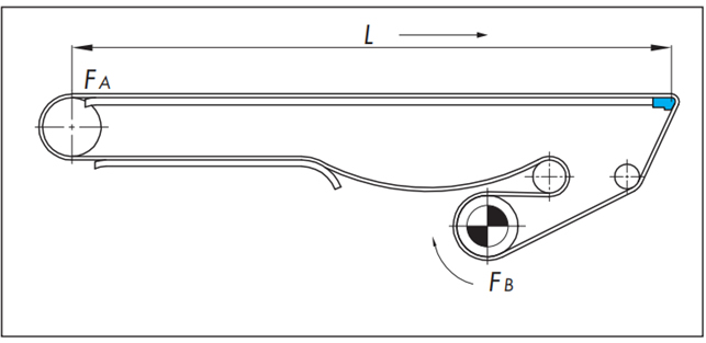
WT2525VG-K形選定例
正逆底部駆動の選定例
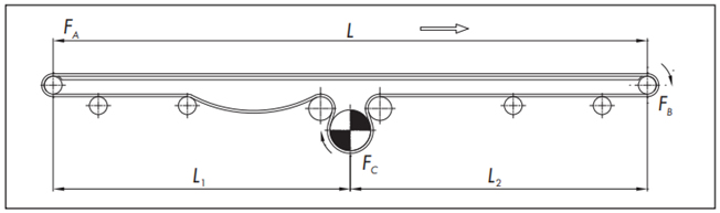
●計算式(SI単位:kN)
・戻り側張力(従動側)
[A部張力:FA]
FA = 1.1m1・L1・μ1 × 9.80665 × 10-3
・搬送側張力
[B部張力:FB]
FB = 1.1{FA + (m1 + m2) × L・μ1 × 9.80665 × 10-3}
・戻り側張力(駆動側)
[C部張力:FC]
FC = FB + m1・L2・μ1 × 9.80665 × 10-3
・チェーン張力
F = FC
●計算例(SI単位)
| 使用条件 | |
|---|---|
| チェーン形式 | WT2525VG-K36-G (m1=9.5×0.9144=8.7kg/m) |
| チェーン幅 | 914.4mm |
| レイアウト | L=10m, L1=6m, L2=4m |
| チェーン速度 | V=10m/min |
| 搬送物 | 段ボールシート 900mm×1800mm×5mm 106.4kg/m2=861.8g/枚×200枚(高さ1m) |
| 搬送物質量(1m長さ当たり) | m2=106.4kg/m2×0.9144m =97.3kg/m |
| 走行レール | 超高分子量ポリエチレン (プラレール) |
| 潤滑 | ドライ |
| 使用雰囲気温度 | 20℃ |
| チェーンと走行レールの動摩擦係数 | μ1=0.25 |
・戻り側張力(従動側)
[A部張力:FA]
FA = 1.1 × 8.7 × 6 × 0.25 × 9.80665 × 10-3 = 0.14kN
・搬送側張力
[B部張力:FB]
FB = 1.1 {0.14 + (8.7 + 97.3) × 10 × 0.25 × 9.80665 × 10-3} = 3.0kN
・戻り側張力(駆動側)
[C部張力:FC]
FC = 3.0 + 8.7 × 4 × 0.25 × 9.80665 × 10-3 = 3.09kN
・使用判定
最大許容張力≧FB'
チェーン幅1m当たりに換算する
FB' = 1000 × FB 914.4 = 3.34(kN/m)
能力線図より許容張力は12.8(kN/m)
12.8(kN/m)≧3.34(kN/m)
選定チェーンは使用可能です。
WT1515F-W形、WT1516F-W形選定例
傾斜搬送(水平+傾斜+水平)の計算
基本的には、傾斜搬送(傾斜のみ)の場合と同様です。水平と傾斜間のカーブ部の作用張力は、角度係数により補正します。
下図の搬送経路について計算例を示します。
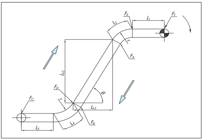
●計算式(SI単位:kN)
L2 = r × αS L4 = r × αS
・戻り側張力
[A部張力:FA]
FA = m1(L1 + L2) μ1・αL × 9.80665 × 10⁻³
L2 = r × αS
[B部張力:FB]
FB = FA + m1(Lh3・μ1 - Lv3) × 9.80665 × 10-3
FB<0の場合は、FB = 0
[C部張力:FC]
FC = 1.1 × (FB + m1(L4 + L5)) × 9.80665 × 10⁻³・αL
L4 = r × αS
・搬送側張力
[D部張力:FD]
FD = {FC + (m1 + m2)(L4 + L5) μ1} × 9.80665 × 10⁻³・αL
L4 = r × αS
[E部張力:FE]
FE = FD + (m1 + m2)(Lh3・μ1 + Lv3) × 9.80665 × 10-3
[F部張力:FF]
FF = {FE + (m1 + m2)(L1 + L2) μ1} × 9.80665 × 10⁻³・αL
L2 = r × αS
・チェーン張力
F = FF
浮上がり防止アタッチメント(タブ)に作用する力
チェーンに浮上がり防止アタッチメント(タブ)を取付ける場合は、浮上がり防止アタッチメント(タブ)1カ所にかかる力Ftの計算を行ってください。
水平から傾斜間のカーブ部でチェーンが浮上がります。浮上がる力はL4部で最大となります。
Ft = FD sin θ/2 nt × 1000
nt = L4部の浮上がり防止アタッチメント(タブ)の総数
nt = L4 30 × (チェーン幅方向のタブの編成カ所)
浮上がり防止アタッチメント(タブ)1カ所にかかる力Ftが240N以下であれば使用可能です。
Ft < 240N
●計算例(SI単位)
| 使用条件 | |
|---|---|
| チェーン形式 | WT1515T-F-W400-LFG-10L-FM50N2 (m1=6.7×0.4=2.7kg/m) |
| チェーン幅 | 400mm |
| レイアウト | L1=0.7m Lv3=1.5m Lh3=0.866m L5=0.7m r=0.5m、角度60°より長さ係数αs=1.0 L2=L4=0.5×1.0=0.5m (揚程 2m) |
| 傾斜角度 | θ=60° |
| チェーン速度 | V=9m/min |
| 搬送物 | アルミ部品、20mm立方、1ヵ所に120個 掻き揚げる |
| 搬送物質量(1m長さ当たり) | m2=30kg/m2(15g/個)×0.4m =12kg/m |
| 走行レール | 超高分子量ポリエチレン (プラレール) |
| アキューム距離 | Ls=4m |
| 潤滑 | ドライ |
| 使用雰囲気温度 | 20℃ |
| チェーンと走行レールの動摩擦係数 | μ1=0.2 (角度係数 αL=1.25) |
・戻り側張力
[A部張力:FA]
FA = 2.7 (0.7 + 0.5) 0.2 × 1.25 × 9.80665 × 10-3
[B部張力:FB]
FB = 0.0079 + 2.7 (0.866 × 0.2 - 1.5) × 9.80665 × 10-3 = -0.027kN
FB < 0より、FB = 0kN
[C部張力:FC]
FC= 1.1 × (0 + 5.1(0.5 + 0.7)) 1.25 × 9.80665 × 10-3・αL = -0.083kN
・搬送側張力
[D部張力:FD]
FD={0.083 + (2.7 + 12)(0.5 + 0.7) 0.2 × 9.80665 × 10-3} × 1.25 = 0.15kN
[E部張力:FE]
FE = 0.15 + (2.7 + 12)(0.866 × 0.2 + 1.5) × 9.80665 × 10-3 = 0.39kN
[F部張力:FF]
FF = {0.39 + (2.7 + 12)(0.7 + 0.5) 0.2 × 9.80665 × 10-3・αL = 0.53kN
・チェーン張力
F = 0.53kN
・使用判定
最大許容張力 ≧ F
F' = 1000 × F 400 = 1.3(kN/m)
能力線図より許容張力は10.5(kN/m)
10.5(kN/m)≧1.3(kN/m)
選定チェーンは使用可能です。
・浮上がり防止アタッチメント(タブ)に作用する力
Ft = 0.15 × sin(60/2) 13 × 1000 = 5.8kN
nt = 400 30 = 13ヶ所
浮上がり防止アタッチメント(タブ)1カ所に掛かる力は5.8Nであるので
5.8N < 240Nとなり使用可能です。
WT3816-K形選定例
特殊コンベヤ(パストライザー/ウォーマー/クーラー)
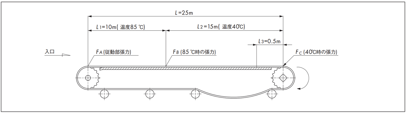
●計算式(SI単位:kN)
・戻り側張力
[A部張力:FA]
FA = 1.1m1・L・μ1 × 9.80665 × 10-3
・搬送側張力
[B部張力:FB]
FB = FA + (m1 + m2) L1・μ1 × 9.80665 × 10-3
[C部張力:FC]
FC = FB + {(m1 + m2) L2・μ1 + m2・L3・μ2} × 9.80665 × 10⁻³
●計算例(SI単位)
| 使用条件 | |
|---|---|
| チェーン形式 | WT3816-K2000-HTW (m1=9.8×2=19.6kg/m) |
| チェーン幅 | 2000mm |
| レイアウト | L=25m, L1=10m, L2=15m |
| チェーン速度 | V=1m/min |
| 搬送物 | ペットボトル1500ml(実) |
| 搬送物質量(1m長さ当たり) | m2=200kg/m2(1530g/個)×2m =400kg/m |
| 走行レール | ステンレス(磨き) |
| アキューム距離 | L3=0.5m |
| 潤滑 | 水(温水) |
| 使用雰囲気温度 | 温水(最高85℃) |
| チェーンと走行レールの動摩擦係数 | μ1=0.35 |
| チェーンと搬送物との動摩擦係数 | μ2=0.35 |
・戻り側張力
[A部張力:FA]
FA = 1.1 × 19.6 × 25 × 0.35 × 9.80665 × 10-3 = 1.85kN
・搬送側張力
[B部張力:FB]
FB = 1.85 + (19.6 + 400) × 10 × 0.35 × 9.80665 × 10-3 = 16.3kN
[C部張力:FC]
FC = 16.3 + {(19.6 + 400) × 15 × 0.35 + 400 × 0.5 × 0.35} × 9.80665 × 10-3 = 38.6kN
・使用判定
各温度域において判定を行う
最大許容張力 ≧ F
・85℃の時
使用張力F = FB'
チェーン幅1m当たりに換算する
FB' = 1000 × FB 2000 = 8.15(kN/m)
能力線図より85℃での許容張力は8.3(kN/m)
8.3(kN/m)≧8.15(kN/m)
選定チェーンは使用可能です。
・40℃の時
使用張力F = FC'
チェーン幅1m当たりに換算する
FC' = 1000 × FC 2000 = 19.3(kN/m)
能力線図より40℃での許容張力は20(kN/m)
20(kN/m)≧19.3(kN/m)
選定チェーンは使用可能です。
各温度域において使用可能です。
