技術資料 大形コンベヤチェーン 選定
9. チェーンに作用する張力の計算方法
運行中にコンベヤチェーンに作用する静的最大張力Tmaxは表3より計算できます。
なお表3のチェーン張力Tの式は、質量M(重量)×摩擦係数を基本としてコンベヤ全体の張力を求めています。
高速コンベヤにおいて急起動、急停止する場合やプッシャーコンベヤなどで搬送物を急激に動かす場合には、慣性力が非常に大きくなります。この場合には慣性力を考慮してチェーン張力、所要動力を求めてください。
計算式はSI単位と重力単位を併記しています。重力単位で張力Tを計算する場合、重力単位の重量(kgf)はSI単位の質量(kg)と同一の数値です。
9.1 用語の説明
| SI単位 | 重力単位 | ||
|---|---|---|---|
| TMAX | チェーンに作用する静的最大張力 | kN | {kgf} |
| T'MAX | 補正チェーン張力 | kN | {kgf} |
| T | チェーンに作用する静的張力 | kN | {kgf} |
| Q | 起り得る最大搬送量 | t/h | {tf/h} |
| V | 搬送速度(チェーン速度) | m/min | m/min |
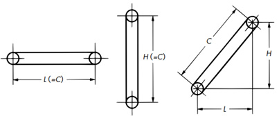
| H | スプロケット中心距離(垂直方向) | m | m |
| L | スプロケット中心距離(水平方向) | m | m |
| C | スプロケット中心距離 | m | m |
| M | 運行部の質量{重量} (チェーン×条数、バケット、エプロンなどの質量{重量}) |
kg/m | {kgf/m} |
| f1 | チェーンとガイドレールとの摩擦係数(表5, 表6) | ||
| f2 | 搬送物と底板、側板との滑り摩擦係数(表7) | ||
| f | 直載せのとき f=1 掻いて運ぶとき f=f2/f1 | ||
| g | 重力加速度 9.80665m/s2 | ||
| W | 搬送物質量{重量} ばらもの W=16.7注×Q/V {W=16.7×Q/V} かずもの W=搬送物質量(kg/個)/積載間隔(m) {W=搬送物重量(kgf/個)/積載間隔(m)} |
kg/m | {kgf/m} |
注)ばらものがチェーン1m当たりに積載されている質量(重量)に換算する係数 16.7=1000/60
※正逆運転を頻繁に行う場合はテークアップによりチェーンのたるみを取る必要がありますので、下記計算式とは異なります。
テークアップでチェーンのたるみを取る場合は、こちらのQ&A6の計算式をご使用ください。
9.2チェーン張力計算 (表3)
| SI単位 | {重力単位} | |||||||||||||||||||||||||||||||||||||||||||||||||||||
|---|---|---|---|---|---|---|---|---|---|---|---|---|---|---|---|---|---|---|---|---|---|---|---|---|---|---|---|---|---|---|---|---|---|---|---|---|---|---|---|---|---|---|---|---|---|---|---|---|---|---|---|---|---|---|
|
水平搬送 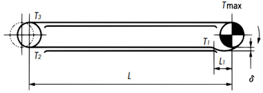
T1 = 1.35 ※1 × M × L1 × g 1000 ......kN T2 = ( L - L1) × M × f1 × g 1000 + T1 ......kN T3 = 1.1 ※2 × T2 ......kN TMAX = (W × f + M ) × L × f1 × g 1000 + T3 ......kN T1 = 1.35 × M × L1 ......{kgf} T2 = ( L - L1) × M × f1 + T1 ......{kgf} T3 = 1.1 × T2 ......{kgf} TMAX = (W × f + M ) × L × f1 + T3 ......{kgf}
|
||||||||||||||||||||||||||||||||||||||||||||||||||||||
|
水平搬送 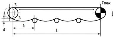
T1 = 1.35 × M × L1× g 1000 + 0.1※ × M × L × g 1000 ......kN T2 = 1.1 × T1 ......kN TMAX = (W × f + M) × L × f1 × g 1000 + T2 ......kN T1 = 1.35 × M × L1 + 0.1※ × M × L ......{kgf} T2 = 1.1 × T1 ......{kgf} TMAX = (W × f + M) × L × f1 ......{kgf}
|
||||||||||||||||||||||||||||||||||||||||||||||||||||||
|
垂直搬送 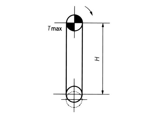
TMAX = (W + M) × H × g 1000 + WT 2 × g 1000 ......kN TMAX = (W + M) × H + WT 2 ......{kgf} |
||||||||||||||||||||||||||||||||||||||||||||||||||||||
|
傾斜搬送 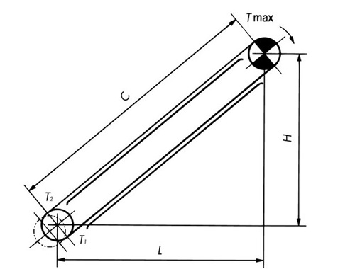
T1 = M(Lf1 - H) × g 1000 ......kN T1 < 0のときはT2 = 0とする T2 = 1.1 × T1 ......kN TMAX = W(Lf1 × f + H) × g 1000 + M(Lf1 + H) × g 1000 + T2 ......kN T1 = M(Lf1 - H) ......{kgf} T1 < 0のときはT2 = 0とする T2 = 1.1 × T1 ......{kgf} TMAX = W(Lf1 × f + H) + M(Lf1 + H) + T2 ......{kgf} |
||||||||||||||||||||||||||||||||||||||||||||||||||||||
|
応用例 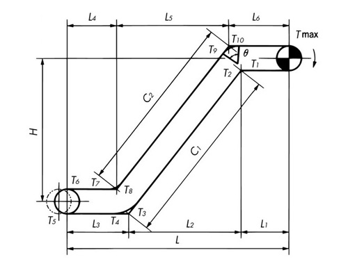
T1= M × L1 × f1 × g 1000 ......kN T2= T1× Kc1 ......kN T3= M(L2f1 - H) × g 1000 + T2 ......kN T4= T3× Kc2 ......kN T3 < 0のときはT4= 0 T5= M × L3 × f1 × g 1000 + T4 ......kN T6= 1.1 × T5 ......kN T7= (M + W × f) × L4 × f1 × g 1000 + T6 ......kN T8= T7× Kc3 ......kN T9= W(L5f1 × f + H) × g 1000 + M(L5f1 + H) × g 1000 + T8 ......kN T10 = T9× Kc4 ......kN TMAX = (M + W × f) × L6 × f1 × g 1000 + T10 ......kN コーナ係数 Kc
T1 = M × L1 × f1 ......{kgf} T2 = T1 × Kc1 ......{kgf} T3 = M(L2f1 - H) + T2 ......{kgf} T4 = T3 × Kc2 ......{kgf} T3 < 0のときはT4 = 0 T5 = M × L3 × f1 + T4 ......{kgf} T6 = 1.1 × T5 ......{kgf} T7 = (M + W × f) × L4 × f1 + T6 ......{kgf} T8 = T7 × Kc3 ......{kgf} T9 = W(L5f1 × f + H) + M(L5f1 + H) + T8 ......{kgf} T10 = T9 × Kc4 ......{kgf} TMAX = (M + W × f) × L6 × f1 + T10 ......{kgf} |
||||||||||||||||||||||||||||||||||||||||||||||||||||||
|
倍速チェーンの例 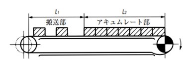
TMAX = 2.1M(L1 + L2) f1 ×
g
1000
+ (W × L1 × f1) TMAX = 2.1M(L1 + L2) f1 + (W × L1 × f1) + (W1 × L2 × f3) ......{kgf}
|
||||||||||||||||||||||||||||||||||||||||||||||||||||||
|
所要動力の計算に用いるチェーン張力Tは下記の式になります。 水平 T = TMAX - T1 垂直 T = TMAX - MH × g 1000 傾斜 T = TMAX - M(H - Lf1) × g 1000 T = TMAX - MH T = TMAX - M(H - Lf1)
・所要動力の計算 1kW = 1kN・m/s kW = T × V 60 1kW = 102kgf・m/s kW = T × V 102 × 60 チェーンとスプロケットの噛み合い、およびスプロケットの回転摩擦抵抗などの動力損失を1割程度とみなす。(1/0.9 = 1.1) 駆動部の伝動機械効率をηとすると、 kW = T × V 60 × 1.1 × 1 η kW = T × V 102 × 60 × 1.1 × 1 η |
||||||||||||||||||||||||||||||||||||||||||||||||||||||
表4. カテナリ張力グラフ
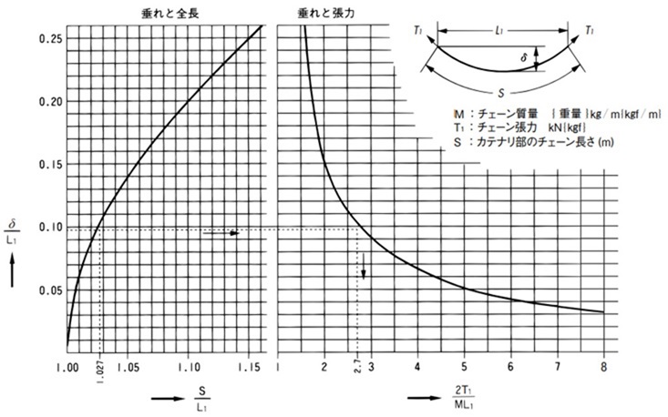
カテナリ張力の求め方
T1 = 1.35 × M × L1 × g 1000 ......kN
この式の1.35は次のとおりです。
カテナリ量10%のとき δ = 0.10L1
上図より
δ
L1
= 0.10 →
2T1
ML1
= 2.7より
T1 = 1.35 × M × L1 ×
g
1000
カテナリ部のチェーン長さの求め方
δ L1 = 0.10 → S L1 = 1.027
S = 1.027L1
表5.チェーンとガイドレールとの転がり摩擦係数(常温) f1
| ローラ径区分 (mm) |
潤滑状態 | 潤滑油切れの場合 | ||
|---|---|---|---|---|
| R,Fローラ | S,M,Nローラ | R,Fローラ | S,M,Nローラ | |
| D<65 | 0.08 | 0.16 | 0.15 | 0.24 |
| 65≦D<100 | 0.08 | 0.15 | 0.14 | 0.23 |
| 100≦D | 0.08 | 0.14 | 0.13 | 0.22 |
| RF-214(例外) | 0.12 | 0.15 | 0.18 | 0.22 |
注)
- 1. 給油はISO VG100~150(SAE30~40)程度の場合
- 2. 塵挨が少なく、常温で室内雰囲気の場合
- 3. トップローラ付チェーンのトップローラと搬送物のf1は、上記のRローラと同じです。
| シリーズ | f1 |
|---|---|
| プラローラシリーズ | 0.08(無給油) |
| ベアリングローラシリーズ | 0.03(潤滑状態) |
| ニードルブシュシリーズ | 0.14(潤滑状態), 0.21(潤滑油切れ) |
| EPC78 | 0.1(潤滑状態), 0.2(水潤滑), 0.25(潤滑油切れ) |
表6.チェーンとガイドレールとの滑り摩擦係数 f1
| 搬送物の温度 ℃ | 潤滑状態 | 潤滑油切れ |
|---|---|---|
| 常温~400 | 0.20 | 0.30 |
| 400~600 | 0.30 | 0.35 |
| 600~800 | 0.35 | 0.40 |
| 800~1000 | - | 0.45 |
表7.搬送物と底板・側板との滑り摩擦係数 f2
| 搬送物 | f2 | 見掛比重 |
|---|---|---|
| スケール | 0.67 | 1.54 |
| 赤鉄鉱 | 0.47 | 2.99 |
| 黄鉄鉱 | 0.58 | 1.54 |
| 鉄滓 | 0.48 | 0.90 |
| スクラップ | 0.73 | 0.54 |
| 鉛鉱粉 | 0.77 | 3.26 |
| 亜鉛鉱粉 | 0.79 | 1.93 |
| ニッケル鉱粉 | 0.45 | 0.92 |
| クロム鉱粉 | 0.51 | 1.14 |
| アルミナ | 0.55 | 0.83 |
| マグネシア | 0.84 | 1.48 |
| 石こう | 0.64 | 0.77 |
| 石英粉 | 0.55 | 1.24 |
| 長石 | 0.55 | 1.36 |
| ドロマイト | 0.55 | 1.62 |
| 粘土 | 0.63 | 0.77 |
| 鋳物砂 | 0.41 | 1.59 |
| 燐鉱石 | 0.42 | 1.51 |
| 生石灰 | 0.46 | 1.53 |
| 消石灰 | 0.63 | 0.69 |
| 石綿 | 0.58 | 0.19 |
| 石灰石 | 0.47 | 0.35~0.55 |
| セメント | 0.54 | 0.60~0.75 |
| セメントクリンカー | 0.46 | 1.30 |
| 木炭 | 0.41 | 0.44 |
| カーボン | 0.53 | 0.30 |
| ピッチ | 0.41 | 0.70 |
| ソーダ灰 | 0.45 | 0.52 |
| みょうばん | 0.63 | 1.01 |
| ポリエチレン | 0.52 | 0.34 |
| ゴム粉 | 0.53 | 0.39 |
| 石けん原料 | 0.27 | 0.65 |
| 尿素 | 0.63 | 0.64 |
| 塩化アンモニア | 0.79 | 0.67 |
| 塩化カルシウム | 0.43 | 0.68 |
| 硫化カルシウム | 0.64 | 1.01 |
| 炭酸カルシウム | 0.49 | 0.88 |
| ウッドチップ | 0.74 | 0.36 |
| 米 | 0.4 | 0.77 |
| 大麦 | 0.71 | 0.39 |
| 小麦 | 0.43 | 0.73 |
| 大豆 | 0.41 | 0.68 |
| トウモロコシ | 0.4 | 0.71 |
| でん粉 | 0.57 | 0.71 |
| 砂糖 | 0.47 | 0.68 |
| 岩塩 | 0.57 | 1.09 |
| 混合飼料 | 0.5 | 0.55 |
| 石炭 | - | 0.30~0.70 |
| コークス | - | 0.30~0.70 |
注)乾燥、湿気により上記の値は変わります。
