技術資料 ドライブチェーン ローラチェーンの取扱
4.ローラチェーンの配置と据付
4.1 速比と巻付角度
ローラチェーン伝動の速比は、7:1までが適当ですが、ごく低速の場合に限り10:1程度まで可能です。なお、小スプロケットとチェーンとの巻付角度は120°以上必要です。
ただし、吊下げ用の場合は90°以上必要です。

図13. 巻付角度
4.2 軸間距離
最短距離は、二つのスプロケットの歯が接触しない距離です。最も好ましい両軸の中心間距離は、使用するローラチェーンのピッチの30~50倍程度です。
ただし、変動荷重がかかるときは20倍以下が適当です。
4.3 たるみ量
1. ローラチェーン伝動では、Vベルトや平ベルト伝動に与えるような初期張力は、必要ありません。
一般にローラチェーンは適当なたるみを持たせて使用します。ローラチェーンを張り過ぎると、ピンとブシュ間に油膜が形成されず、ローラチェーンや軸受の損傷を早めます。
また、たるみ過ぎるとローラチェーンに振動や、スプロケット へのかみこみが発生し、ローラチェーンとスプロケットの両方を損傷します。
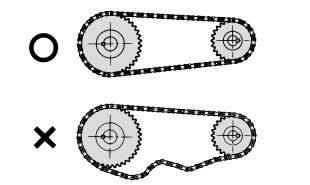
図14. たるみ例
2. ローラチェーン伝動では、なるべく下側をたるみ側とします。
適当なたるみ量は、たるみ側の中央を手で直角方向へ動かし、その距離SS'がスパンABの約4%程度になる量です。
(例:スパンの長さ800mmの場合のたるみ量は、800mm × 0.04 = 32mmとなります。)
次のような場合は、2%程度にします。
- ・垂直伝動、あるいはそれに近い配置の場合
- ・軸間距離が1m以上の場合
- ・重荷重でしばしば起動する場合
- ・急に逆転する場合
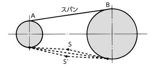
図15. たるみ量
3. ローラチェーンは、使い始めてから数十時間までは、各部接触面のなじみにより0.05%程度伸びます。
そのため、ローラチェーンのたるみ量の調節が必要になることがあります。
緊張装置で調節できる場合は、それを使用します。緊張装置がない場合は、軸受を移動させてたるみ量を調整します。チェーンがよくなじんでくると、伸びは少なくなります。
4.4 軸の平行度と水平度
スプロケットの取付精度は、ローラチェーンの円滑な動きに影響を持ち、ローラチェーンの寿命を左右します。
1. 水準器で軸の水平度をだします。
精度は、±1300になるように調整を行います。
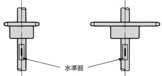
図16. 軸の水平度
2. スケールで軸の平行度をだします。
軸の平行度は、±1300 ≧ A - BLになるように調整を行います。
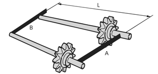
図17. 軸の平行度
3. ストレートエッジやイージーレーザーなど平面の平行度を測定できる器具を用いて、一対のスプロケットが同一平面にあるように修正します。スプロケットの軸間距離により、次の値になるように取付けます。
- 1mまで:±1mm
- 1~10m:± 軸間距離(mm)1,000
- 10m以上:±10mm
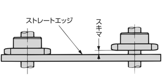
図18. スプロケットの面合わせ
スプロケットは、パワーロックやロックスプロケット、キーで軸に固定します。
カラーやセットボルトなどの調整部品が必要な場合もあります。
4.5 配置
1. 一般的な配置
ローラチェーン伝動の配置は、両スプロケットの中心を結ぶ線が水平に近いのが理想的です。垂直に近い配置ではローラチェーンが少し伸びてもスプロケットから外れやすくなるため、アイドラかテンショナをご使用ください。傾斜角は、出来るだけ60°以内になるように配置します。
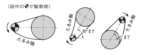
図19. 一般的な配置
2. 配置に関する留意点
・上側がたるみ側の場合
中心距離が短い場合は、軸受を移動してスプロケットの中心距離を伸ばし、張り気味に調整します。
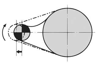
図20. 中心距離が短い場合の調整例
中心距離が長い場合は、たるみの内側から中間アイドラを入れてローラチェーンを受けます。
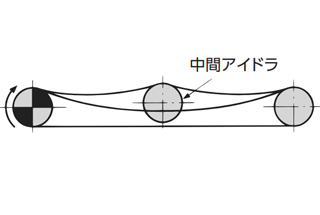
図21. 中心距離が長い場合の調整例
・チェーン速度が速く、変動荷重がかかる場合
ローラチェーンの固有振動数と被動機の衝撃周期、あるいはローラチェーンのコーダルアクション(多角形運動によるローラチェーンの上下動)などが同調して、ローラチェーンが振動することがあります。
このような場合には、振動防止のためにガイドストッパ(NBR・超高分子ポリエチレン製)などの振れ止めで振動を抑えます。
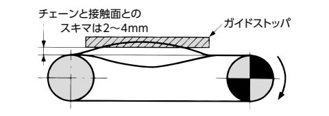
図22. 振動防止の例
・中心線が垂直の場合
余分のたるみ量を自動的に調整できるテンショナを取付けて、スプロケットに確実に噛み合うようにします。駆動軸が下側の場合には特に必要です。

図23. 垂直伝動の場合の調整例
4.6 カーブドチェーンの据付
1. ガイドの設置
カーブドチェーンは、RSローラチェーンに比べて自由度があるため、スプロケットには真っすぐに噛み合うよう、チェーンにガイドを設けます。
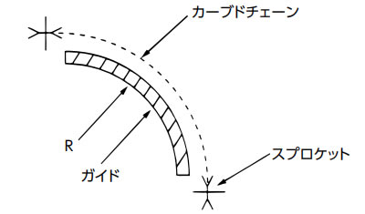
図24. ガイド図
2. 最小横曲がり半径(r)
ガイドのR寸法が下表の最小横曲がり半径以上になるようにガイドを設置します。
| 品名 | 最小横曲り半径(r) |
|---|---|
| RS40-CU-1 | 350 |
| RS50-CU-1 | 400 |
| RS60-CU-1 | 500 |
| RS80-CU-1 | 600 |
| RS40-LMCCU-1 | 400 |
| RS50-LMCCU-1 | 500 |
| RS60-LMCCU-1 | 600 |
| 品名 | 最小横曲り半径(r) |
|---|---|
| RS40-CUSS-1 | 400 |
| RS50-CUSS-1 | 500 |
| RS60-CUSS-1 | 600 |
| RS80-CUSS-1 | 800 |
