技術資料 ドライブチェーン ローラチェーンの選定
10. チェーン式ピンギヤ駆動選定法 注:チェーン式ピンギヤとは
1. 速度の考慮
本選定法は、相対チェーン速度が50m/min以下の場合に適用できます。
(50m/min以下のときの対応例)
- 直線用途で検討されている場合:
ロール駆動などの巻きかけ方式に変更 - 巻き付け用途で検討されている場合:
チェーン取付径を小さく変更
| 相対チェーン速度 m/min |
ピンギヤ 速度係数 |
|---|---|
| 15未満 | 1.0 |
| 15以上30未満 | 1.2 |
| 30以上50未満 | 1.4 |
2. スプロケットの考慮
13歯以上のチェーン式ピンギヤ用スプロケットをご使用ください。
18歯を推奨します。
3. チェーン式ピンギヤ駆動の例
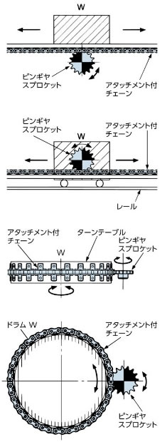
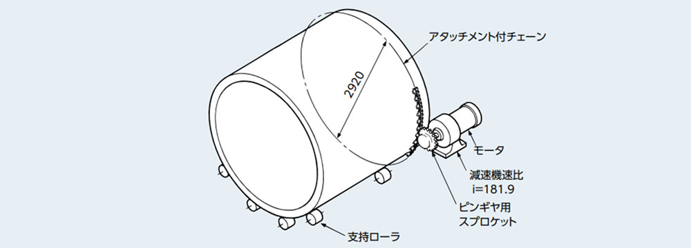
チェーン式ピンギヤ駆動選定例
| SI単位 |
|---|
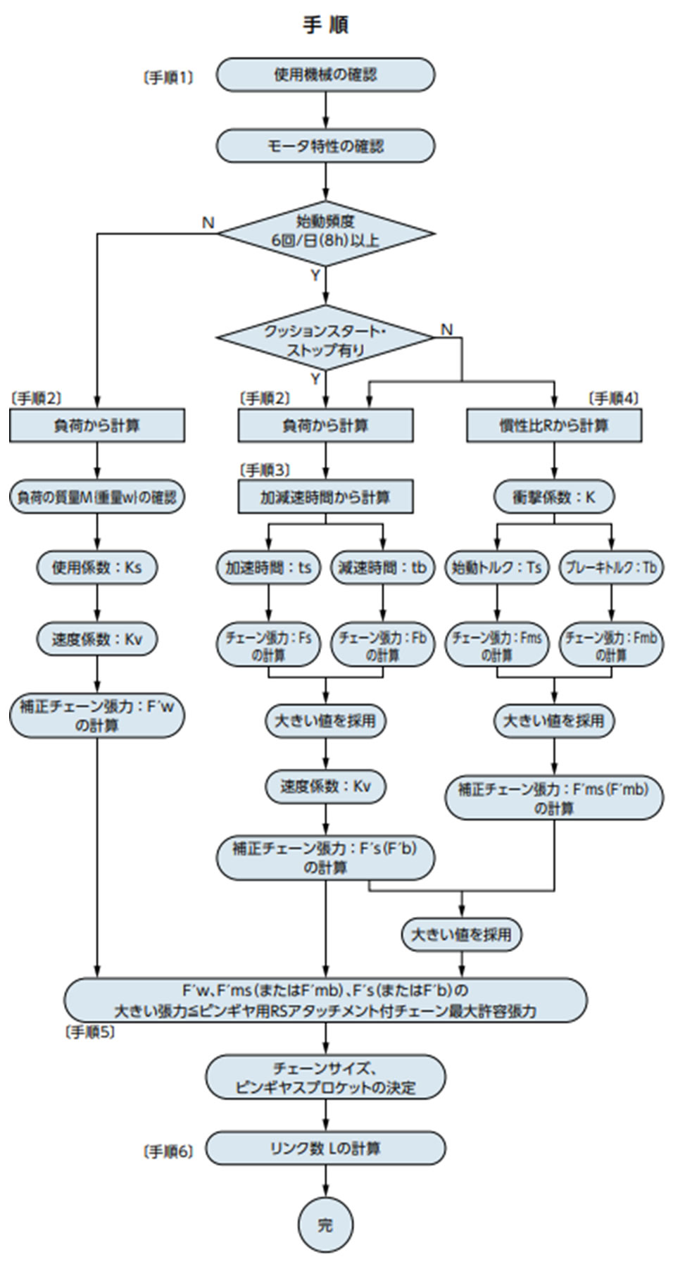
手順1 使用機械、モータ特性の確認
手順2 負荷から計算ピンギヤ駆動スプロケットの回転速度 n = 1750 ×
1
181.9
相対チェーン速度 V =
220 × π × 9.6
1000
= 6.6 (m/min) 切断機のため多少の衝撃と仮定 負荷の質量不明のため駆動側トルクより作用張力を求める。 モータの定格トルク
ピンギヤ駆動スプロケット軸トルク チェーン作用張力 F = 2T d 1000 = 2 × 1.49 220 1000 = 13.6 (kN)
補正チェーン張力 F'w = F × Ks × Kv = 13.6 × 1.3 × 1.0 手順3 加減速時間から計算作用トルク Tm =
Ts + Tb
2 × 100
× Tn =
290 + 305
2 × 100
× 0.00819
負荷不明のためモータの定格トルクTn = Tℓとし、
加速時間 ts =
(Im + Iℓ) × n1
9550 × (Tm - Tℓ)
=
(0.00425 + 0.00072) × 1750
9550 × (0.0244 - 0.00819)
モータのブレーキトルク Tb = 0.00819 × 1.8 = 0.0147 (kN・m)
減速時間 tb =
(Im + Iℓ) × n1
9550 × (Tb + Tℓ)
モータ軸換算負荷の慣性モーメント IIℓ = 0.00072 (kg・m2) Fw = F= 13.6 (kN) [手順2で求めた値] tb < tsのため減速時のチェーン張力を求めます。 モータ軸の角速度 ω = 2π × n1 = 2π × 1750 = 11000 (rad)
モータ軸の角減速度 ωb =
ω
60 × tb
=
11000
60 × 0.040
減速時のチェーン張力 Fb =
Iℓ × ωb × i
1000 ×
d
(2 × 1000)
+ Fw 減速時の補正チェーン張力
F'b = Fb × Kv = 19.1 × 1.0 手順4 慣性比Rから計算慣性比 R = Iℓ Im = 0.00072 0.00425 = 0.17 表4より衝撃係数 K = 0.23 始動時のチェーン張力 Fms =
Ts × i
d
2 × 1000
× 100
× Tn 制動時のチェーン張力 Fmb =
Tb × i
d
2 × 1000
× 100
× Tn × 1.2 Fms > Fmbより 手順5 (1)(2)(3)を比較(1)(2)(3)を比較し最大作用張力(2)の19.1kNを満足する最大許容張力を持つピンギヤ用アタッチメント付チェーンを選定します。 RS120アタッチメント付チェーンのピンギヤ使用時の最大許容張力 ピンギヤ用スプロケットのピッチ円直径~Φ220~よりスプロケットは歯数18 手順2、3、4を再計算します。 [手順2] F = 2T d 1000 = 2 × 1.49 222.49 1000 = 13.4 (kN) F'w = F × Ks × Kv = 13.4 × 1.3 × 1.0 = 17.4 (kN) [手順3] Fb =
Iℓ × ωb × i
1000 ×
d
(2 × 1000)
+ Fw 減速時の補正チェーン張力 F'b = Fb × Kv = 18.8 × 1.0 = 18.8 (kN) [手順4] Fms =
Ts × i
d
2 × 1000
× 100
× Tn 補正チェーン張力 F'ms = Fms × K × Kv = 38.8 × 0.23 × 1.0 = 8.92 (kN) いずれの補正チェーン張力も最大許容張力内であることから、ピンギヤ用アタッチメント付チェーンとピンギヤ用スプロケットが使用可能です。 [手順6] リンク数Lの計算 リンク数Lの計算 242リンク基準長さ(38.1 × 242 = 9220.2mm)に相当する |
| {重力単位} |
|---|
手順1 使用機械、モータ特性の確認
手順2 負荷から計算ピンギヤ駆動スプロケットの回転速度 n = 1750 ×
1
181.9
相対チェーン速度 V =
220 × π × 9.6
1000
= 6.6 (m/min) 切断機のため多少の衝撃と仮定 負荷の質量不明のため駆動側トルクより作用張力を求める。 モータの定格トルク
ピンギヤ駆動スプロケット軸トルク チェーン作用張力 F = 2T d 1000 = 2 × 152 220 1000 = 1380 (kgf)
補正チェーン張力 F'w = F × Ks × Kv = 1380 × 1.3 × 1.0 手順3 加減速時間から計算作用トルク Tm =
Ts + Tb
2 × 100
× Tn =
290 + 305
2 × 100
× 0.835
負荷不明のためモータの定格トルクTn = Tℓとし、
加速時間 ts =
(GD2m + GD2ℓ) × n1
375 × (Tm - tℓ)
=
(0.017 + 0.00288) × 1750
375 × (2.48 - 0.835)
モータのブレーキトルク Tb = 0.835 × 1.8 = 1.50 (kgf・m)
減速時間 tb =
(GD2m + GD2ℓ) × n1
375 × (Tb + Tℓ)
モータ軸換算負荷 GD2 GD2ℓ = 0.00288 (kgf・m2) Fw = F = 1380 (kgf) [手順2で求めた値] tb < tsのため減速時のチェーン張力を求めます。 モータ軸の角速度 ω = 2π × n1 = 2π × 1750 = 11000 (rad)
モータ軸の角減速度 ωb =
ω
60 × tb
=
11000
60 × 0.040
減速時のチェーン張力 Fb =
GD2ℓ / 4 × ωb × i
d
(2 × 1000)
× G
+ Fw 減速時の補正チェーン張力
F'b = Fb × Kv = 1940 × 1.0 手順4 慣性比Rから計算慣性比 R = GD2ℓ GD2m = 0.00288 0.017 = 0.17 表4より衝撃係数 K = 0.23 始動時のチェーン張力 Fms =
Ts × i
d
2 × 1000
× 100
× Tn 制動時のチェーン張力 Fmb =
Tb × i
d
2 × 1000
× 100
× Tn × 1.2 Fms > Fmbより 手順5 (1)(2)(3)を比較(1)(2)(3)を比較し最大作用張力(2)の1940kgfを満足する最大許容張力を持つピンギヤ用アタッチメント付チェーンを選定します。 RS120アタッチメント付チェーンのピンギヤ使用時の最大許容張力 ピンギヤ用スプロケットのピッチ円直径~Φ220~よりスプロケットは歯数18 手順2、3、4を再計算します。 [手順2] F = 2T d 1000 = 2 × 152 222.49 1000 = 1370 (kgf) F'w = F × Ks × Kv = 1370 × 1.3 × 1.0 = 1780 (kgf) [手順3] Fb =
GD2ℓ/4 × ωb × i
d
(2 × 1000)
× G
+ Fw 減速時の補正チェーン張力 F'b = Fb × Kv = 1930 × 1.0 = 1930 (kgf) [手順4] Fms =
Ts × i
d
2 × 1000
× 100
× Tn 補正チェーン張力 F'ms = Fms × K × Kv = 3960 × 0.23 × 1.0 = 911 (kgf) いずれの補正チェーン張力も最大許容張力内であることから、ピンギヤ用アタッチメント付チェーンとピンギヤ用スプロケットが使用可能です。 [手順6] リンク数Lの計算 リンク数Lの計算 242リンク基準長さ(38.1 × 242 = 9220.2mm)に相当する |
選定結果
| チェーン形番 | RS120-2LK1+242L-JR |
| スプロケット形番 | RS120-1□18TQ-G (□にはハブ形式が入ります) |
