技術資料 ドライブチェーン ローラチェーンの選定
11. 慣性モーメントの求め方
回転運動体
| 形状 | 概要 | I(慣性モーメント)算出法 (SI単位) |
{GD2算出法重力単位} |
|---|---|---|---|
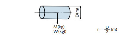
| 直円柱 |
|
I = 1 2 Mr2 (kg・m2) | GD2 = 1 2 WD2 (kgf・m2) |
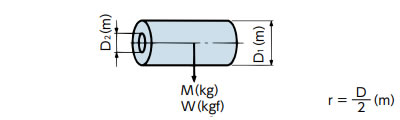
| 中空直円柱 |
|
I = 1 2 M(r12+r22) (kg・m2) |
GD2 =
1
2
W(D12 + D22) (kgf・m2) |
| SI単位 | {重力単位} | |
|---|---|---|
| 慣性モーメント(I)とはずみ車効果(GD2) | 1kg・m2(I) | 4kgf・m2(GD2) |
直線運動体
| 駆動形式 | 概要 | I(慣性モーメント)算出法 (SI単位) |
{GD2算出法重力単位} |
|---|---|---|---|
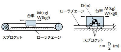
| チェーン |

|
I = Mr2(kg・m2) | GD2 = WD2(kgf・m2) |
| 台車駆動 |
|
I = Mr2(kg・m2) | GD2 = WD2(kgf・m2) |
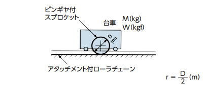
| ピンギヤ駆動 |
|
I = Mr2(kg・m2) | GD2 = WD2(kgf・m2) |
| 吊下げ伝動 |
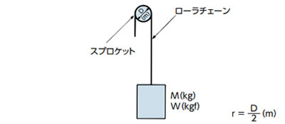
|
I = Mr2(kg・m2) | GD2 = WD2(kgf・m2) |
|
負荷の慣性モーメントをモータ軸換算する場合
|
負荷の慣性モーメント I Iℓ = n2 n1 2 I = I i2 (kg・m2) Iℓ = M V 2πn1 2 (kg・m2) |
負荷の慣性モーメント GD2 GD2ℓ = n2 n1 2 GD2 = GD2 i2 (kgf・m2) GD2ℓ = W V πn1 2 (kgf・m2) |
|
注)上記は、スプロケット、チェーンの質量は含んでいません。
