Cable carrier Plastic series TKP Series Major Specifications
TKP35H32-30W25R60
Construction
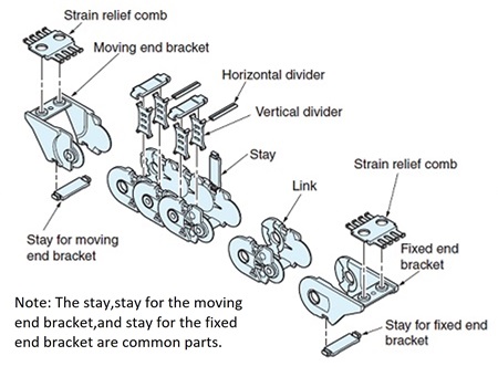
[Click to enlarge ]
PDF Outline Drawing
Contact us for details.
DXF drawings / 3D CAD data
Please re-set the Inner width etc. on the linked screen.
| ※ | The CAD data contained herein is made available to you via the CAD drawing library; PARTcommunity is provided by CADENAS WEB2CAD Co. |
| ※ | Please direct your inquiries regarding the CAD data service or PARTcommunity to: CADENAS WEB2CAD Co. TEL: +81 (3) 5961-5031 FAX: +81 (3) 5961-5032 |
この製品は環境配慮材を使用しています。
Catalogs ・Instruction Manuals
Basic Package
| Maximum travel length m | 2 |
|---|---|
| Cable/hose maximum outer diameter mm | 22 |
| Cable/hose maximum mass kg/m | 2 |
| Maximum travel speed m/min ※1 | 300 |
| Operating Temperature Range | -40゚C~80゚C |
| Material | Engineering plastic (black) |
| Mass kg/m | 0.6 |
| No. of links per unit | 25 |
Notes
1.150 m/min for support roller arrangement.
2.Cannot be used in acidic or alkaline environments.
| Special types | |
|---|---|
| Gliding arrangement | Not available |
| Circular travel arrangement | Available |
Allowable load graphs
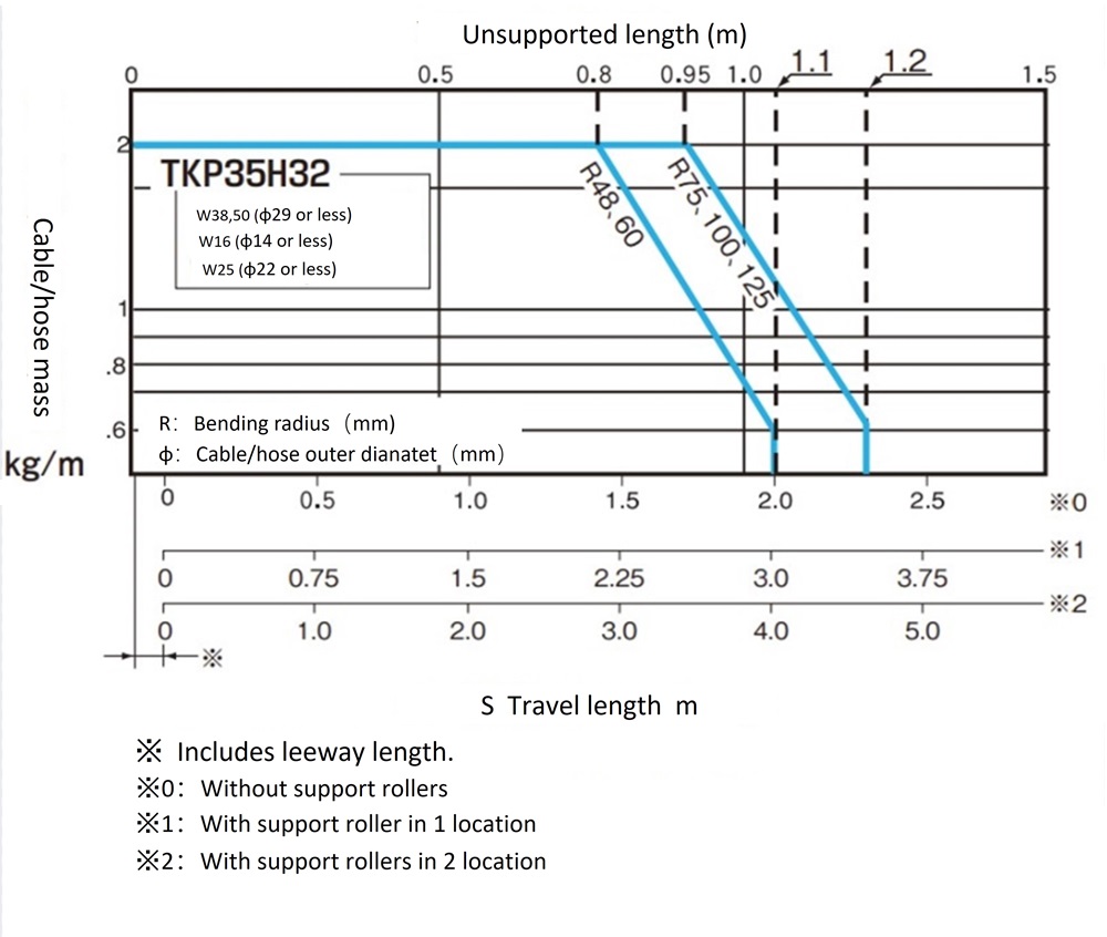
[Click to enlarge ]
Divider
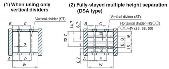
[Click to enlarge ]
A:Distance from center of vertical divider to end face of link
B:Gap between vertical divider and link
P:Distance between the centers of neighboring vertical dividers
C:Gap between neighboring vertical dividers
Vertical divider
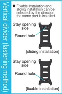
[Click to enlarge ]
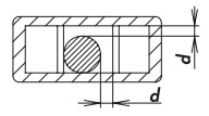
Make the gap between cables/hoses and the divider or link (d in the figure above) to whichever of the following two values is larger: 2 mm or greater or the outer diameter of the cable or hose x 0.1.
| Model No. | Type | Fixing method | A mm | B mm | P mm | C mm | Mass g/each |
Standard Price | Delivery | DXF drawings 3D CAD data |
|---|---|---|---|---|---|---|---|---|---|---|
| TKP35H32-ST | Sliding/Fixable dual-use type | Sliding installation | 3~21 | 2~20 | 6~44 | 4~42 | 2 | Contact us for details. | Contact us for details. | DXF・3DCAD |
| Fixable installation | 4.5 - 14.5 (2mm increments) | 3.5 - 13.5 (2mm increments) | 6 - 16 (2mm increments) | 4 - 14 (2mm increments) |
| Model No. | Mass g/each |
Standard Price | Delivery | DXF drawings 3D CAD data |
|---|---|---|---|---|
| TKP35H32-HS25 | 1 | Contact us for details. | Contact us for details. | DXF・3DCAD |
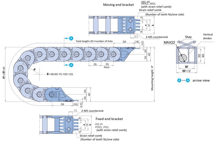
Dimension drawings
[Click to enlarge ]
| Pitch P |
Inner height | Inner width W |
Bending radius R |
Mounting height H' |
Leeway length K |
Number of comb teeth nz | a | b | c |
|---|---|---|---|---|---|---|---|---|---|
| 35 | 32 | 25 | 60 | 170~190 | 35 | 3 | 12 | 37 | 25 |
Notes
1.Design and install according to the mounting height H' dimension.
Calculating no. of links
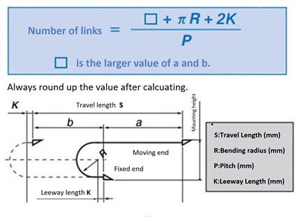
[Click to enlarge ]
Bracket

[Click to enlarge ]
| Moving end side (α) | 17 |
|---|---|
| Fixed end side (β) | 17 |
Moving end bracket
| Model No. | Material | Mass g/each | Standard Price | Delivery |
|---|---|---|---|---|
| TKP35H32W25-MO | Engineering plastic (black) | 24 | Contact us for details. | Contact us for details. |
| TKP35H32W25-MI | Engineering plastic (black) | 24 | Contact us for details. | Contact us for details. |
Moving end bracket (with strain relief combs)
| Model No. | Material | Mass g/each | Standard Price | Delivery |
|---|---|---|---|---|
| TKP35H32W25-MOCL | Engineering plastic (black) | 28 | Contact us for details. | Contact us for details. |
| TKP35H32W25-MICL | Engineering plastic (black) | 28 | Contact us for details. | Contact us for details. |
Fixed end bracket
| Model No. | Material | Mass g/each | Standard Price | Delivery |
|---|---|---|---|---|
| TKP35H32W25-FO | Engineering plastic (black) | 26 | Contact us for details. | Contact us for details. |
| TKP35H32W25-FI | Engineering plastic (black) | 26 | Contact us for details. | Contact us for details. |
Fixed end bracket (with strain relief combs)
| Model No. | Material | Mass g/each | Standard Price | Delivery |
|---|---|---|---|---|
| TKP35H32W25-FOCL | Engineering plastic (black) | 30 | Contact us for details. | Contact us for details. |
| TKP35H32W25-FICL | Engineering plastic (black) | 30 | Contact us for details. | Contact us for details. |
Strain relief combs
| Model No. | Mass g/each | Standard Price | Delivery |
|---|---|---|---|
| TKP35H32W25-CL-P | 4 | Contact us for details. | Contact us for details. |
・Plastic bracket MO and MI, FO and FI are common parts.
※Click here for details on accessories such as strain reliefs
Contact Information
Online Inquiries
For inquiries in English, visit the Inquiries page on our Tsubaki Group website.
When purchasing this product outside of Japan, please contact nearest overseas office using the link below.
